62-11640 8–28
the gasket is installed in the body groove, and
torque the body screws 80 to 97 inch/lbs (9 to 11
Nm).
3. Leak check, evacuate & dehydrate, and charge
system as required. Refer to Section 8.6.2,
Section 8.6.3 & Section 8.6.4.
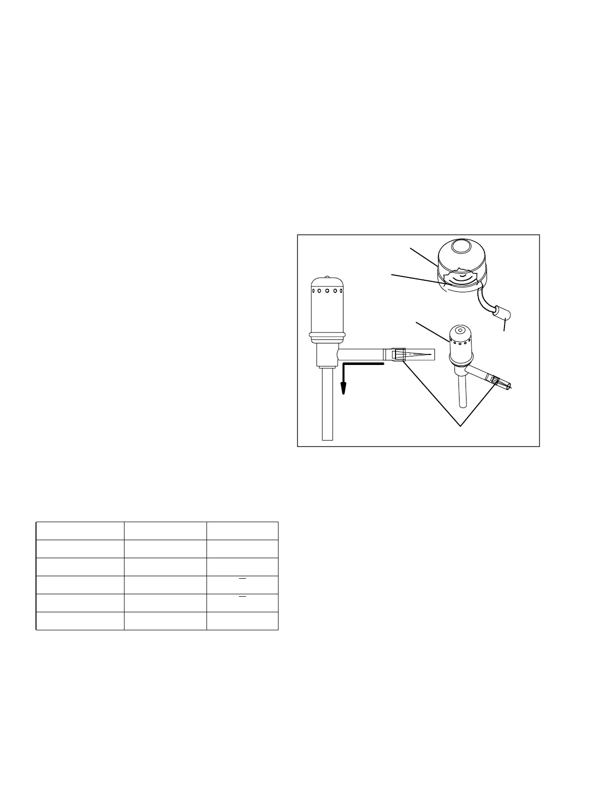
8.8.7 Expansion Valves, EVXV & ECXV
The electronic expansion valves (EVXV = evaporator
expansion valve & ECXV = economizer expansion
valve see Figure 8.24) are automatic devices which
maintain constant superheat of the refrigerant gas
leaving the evaporator/economizer regardless of suc-
tion pressure. The valve functions are: (a) automatic
response of refrigerant flow to match the evaporator
load and (b) prevention of liquid refrigerant return to the
compressor. Unless a valve is defective, it seldom
requires any maintenance.
NOTE
As a preliminary valve check, ensure the coil
is snapped down fully, and the internal coil
retention tab is properly seated in one of the
valve body dimples. Also, check for a tem-
perature drop at the valve inlet strainer loca-
tion, indicating the strainer is restricted or
plugged.
a. Diagnostics − Microprocessor or Wiring
1. Locate the wires on the harness side labeled:
EXVA, EXVB, EXVC, EXVD and EXVE
or
ECVA, ECVB, ECVC, ECVD and ECVE
These will correlate to the connector pins
labeled A, B, C, D and E. Refer to Table 8–2.
2. To test the EVXV, place the SROS in the Start/
Run position. DO NOT ALLOW THE UNIT TO
START. When the Message Center displays
“SMV CLOSING”, measure the AC voltage
between pins E & A and then between E & B, E
& C and E & D.
3. Test the ECXV, start the unit and bring the set-
point well below the refrigerated compartment
temperature to ensure the unit is operating in
Economized Mode. Measure the AC voltage
between pins E & A and then between E & B, E
& C and E & D. A voltage should be read by the
digital voltmeter for each pair of wires. If the
reading is present on all of the wire pairs there is
a good signal.
4. If the reading is not present on one or more of
the wire pairs, check the wiring between the
valve and the valve connector, or check the
Control System for proper model number Con-
figuration.
Figure 8.24 Evaporator Expansion Valve
b. Diagnostics - Stepper Motor
The valve stepper motor may be tested using a stepper
motor drive tester or ohmmeter.
1. To test with a stepper motor drive tester (Carrier
Transicold part number 07−00375−00SV), con-
nect the 5 pin test cable to the valve connector
(see Figure 8.25), and the cable wires to the
tester in accordance with wire and terminal
color. (if a 5 pin tester cable is required, order
Carrier Transicold part number 07−00375−11.)
2. Set the step rate to 50 steps per second and
either open or close the valve. Each red LED
should light sequentially until all four are illumi-
nated. Any LED failing to illuminate indicates an
open on that leg and a need to replace the drive.
3. To test with an ohmmeter, check the winding
resistance between connector pin A & E, B & E,
C & E and then between D & E. In normal ambi-
ent, the resistance between the pins should be
46 ohms. If an infinite or zero reading is
observed, the piston and drive motor assembly
is to be replaced.
Table 8–2 Expansion Valve Connections
Connector Pin Wire Color Winding
A ORANGE A
B RED B
C YELLOW A
D BLACK B
E GREY COM (+12V)
FLOW
DIRECTION
Coil
Boot
Coil
Electronic
Expansion
Valve
Strainer
Five Pin
Connector

 Loading...

