8–45 62-11640
38. If equipped, reconnect the Generator Thermis-
tor.
39. Reconnect the radiator hose “p” clamp.
40. Using new hardware, reinstall the exhaust to the
manifold and torque hardware 22 to 24 ft/lbs
(29.8 to 32.5 Nm). Reinstall the heat shield.
41. Reconnect the air intake hose at the intake
manifold connection. Refasten the connectors to
the intake manifold connection.
42. Reinstall the positive & negative battery cables.
When reinstalling the positive wire to the starter
torque to 6 to 8 ft−lbs (9.4 Nm). See Figure
8.46.
43. Re−seal the positive & negative battery cable
connections using Red glyptol varnish, Carrier
P/N 07−00479−00.
44. Reinstall the hardware attaching the generator
ground strap at the frame and the harness
ground wire at the back of the generator.
Figure 8.46 Positive Starter Wire Installation
45. Replace the Air Cleaner Assembly and hoses.
46. Reinstall the battery cable connections at the
battery.
47. Reinstall the doors
48. Remove the lockout/tagout equipment, start unit
and run Pretrip.
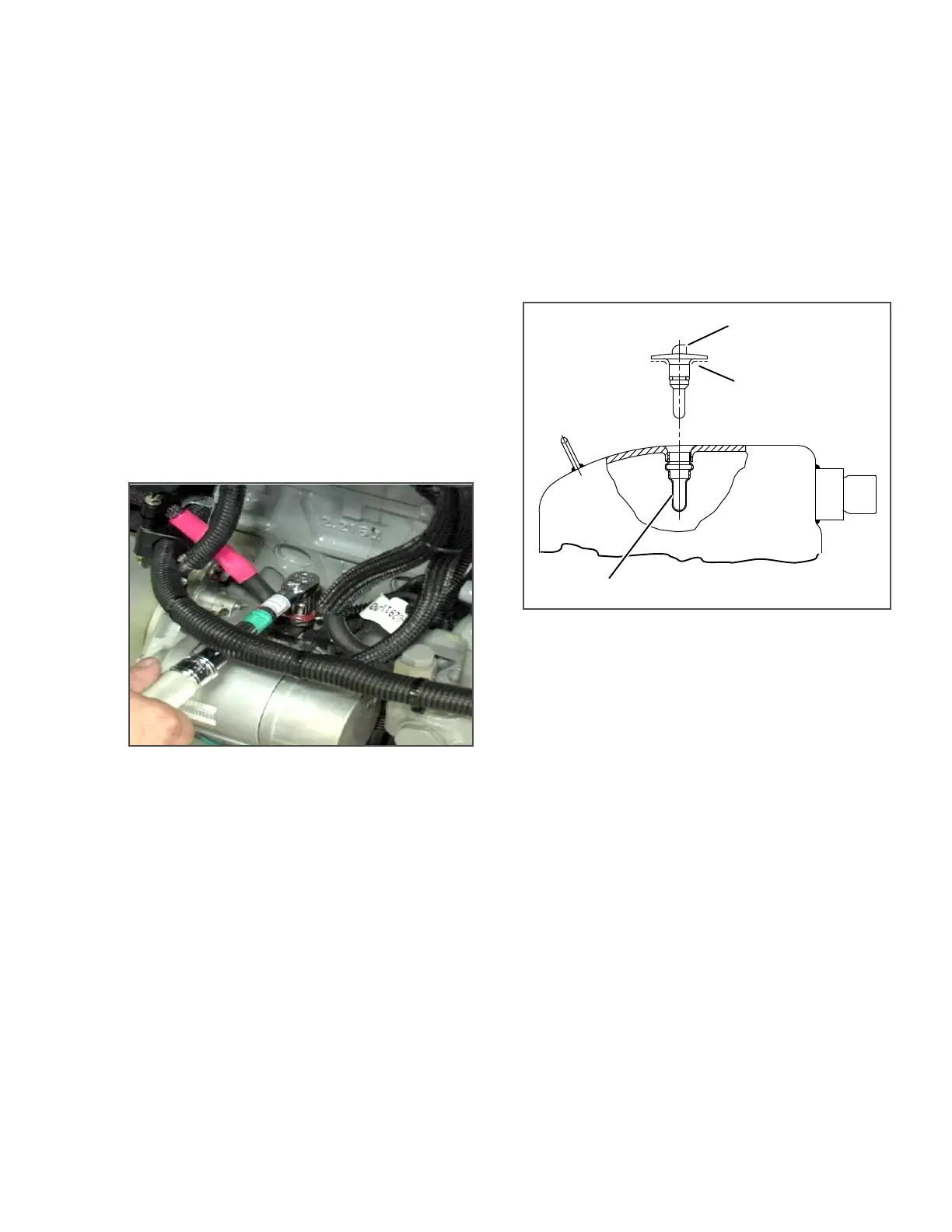
8.9.14 Compressor Discharge Temperature Sen-
sor
Values for testing the sensor, in accordance with stan-
dard procedures, are provided in Table 8–4. To
replace the compressor discharge temperature sensor
(see Figure 8.47) do the following:
1. Ensure the unit will not start automatically by
disabling any two way communication and plac-
ing the STOP/RUN-OFF switch in the OFF posi-
tion. Disconnect the high voltage source and
lockout/tagout the receptacle.
2. Remove the existing sensor. Clean all silicone
sealer and dielectric compound from the sensor
well. Ensure well is clean and dry. Top of com-
pressor, where the sensor seals, must also be
clean and dry.
Figure 8.47 Compressor Discharge Temperature
Sensor
3. Using the syringe supplied with the replacement
sensor, squeeze all of the dielectric compound
into the sensor well.
4. Place a bead of the silicone sealer supplied with
the replacement sensor around the sensor seal-
ing ring. Insert sensor into the well with the
leads parallel to the suction fitting.
5. Reconnect sensor connector and run a Pretrip
to test.
8.9.15 Sensor Checkout
An accurate ohmmeter must be used to check resis-
tance values shown in Table 8–3 or Table 8–4.
Due to variations and inaccuracies in ohmmeters, ther-
mometers or other test equipment, a reading within 2%
of the chart value would indicate a good sensor. If a
sensor is bad, the resistance reading will usually be
much higher or lower than the resistance values given
in the tables.
Two preferred methods of determining the actual test
temperature at the sensor, is an ice bath at 32°F (0°C)
or a calibrated temperature tester.
SENSOR WELL
SENSOR
SILICONE BEAD

 Loading...

