62-11640 8–22
8.7 COMPRESSOR SERVICE
WARNING
!
Before removal of the compressor, relieve
the internal pressure by very carefully
loosening the couplings to break the seal.
NOTICE
The scroll compressor achieves low suc-
tion pressure very quickly. Do not use the
compressor to evacuate the system below
0 psig. Never operate the compressor with
the suction or discharge service valves
closed (frontseated). Internal damage will
result from operating the compressor in a
deep vacuum.
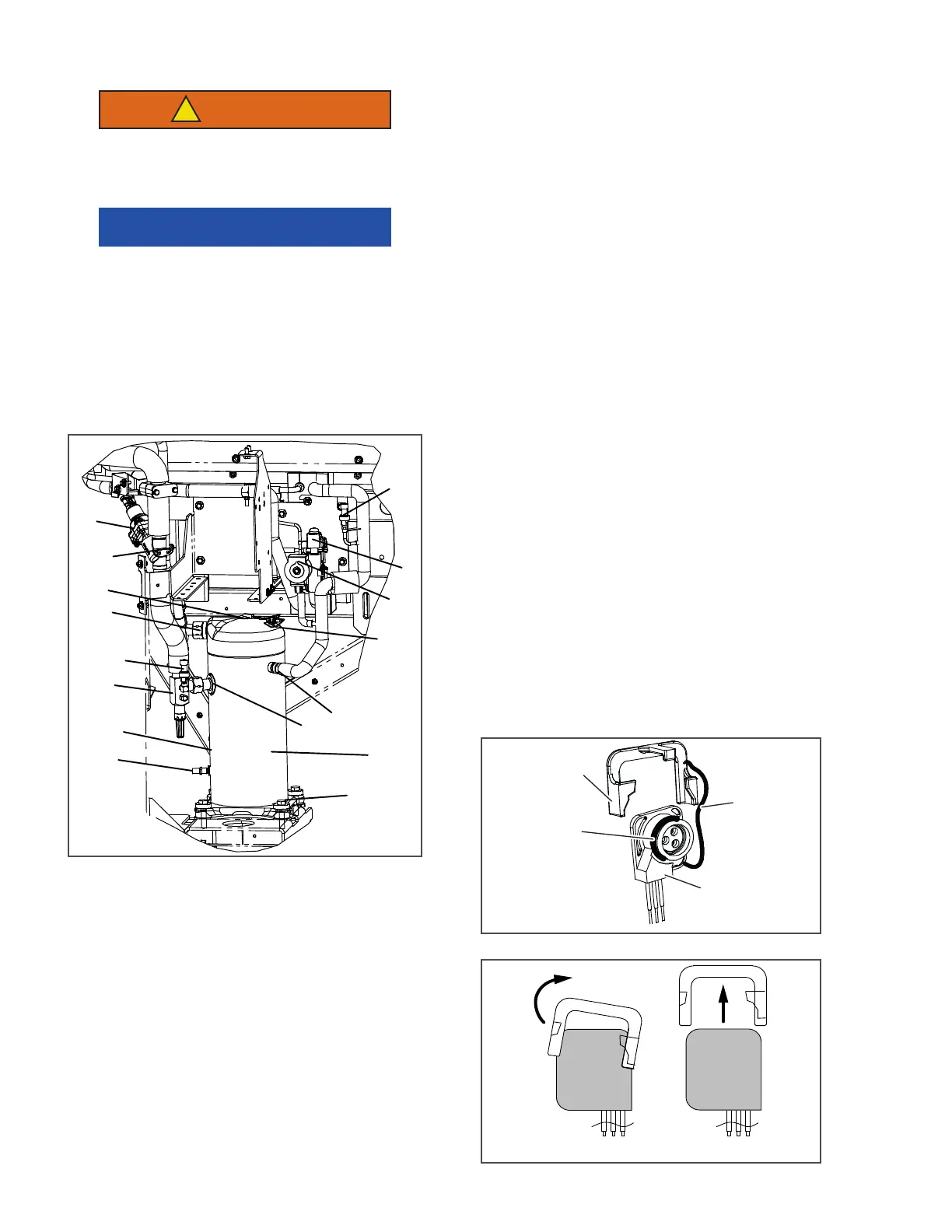
Figure 8.18 Compressor Kit
1. Remove refrigerant charge. Refer to Section
8.6.2
2. Ensure the unit will not start automatically by
disabling any two way communication and plac-
ing the STOP/RUN-OFF switch in the OFF posi-
tion. Disconnect the high voltage source and
lockout/tagout the receptacle.
3. Frontseat discharge and suction service valves
to help protect the remainder of the system.
4. If necessary, remove all remaining refrigerant
from compressor using refrigerant recovery sys-
tem. Refrigerant out gassing from compressor
oil can build pressure when service valves are
closed. Additional reclamation may be needed
to insure no refrigerant exists in the compressor.
5. Remove the Rotalock fittings from the suction
and discharge service connections, and uncou-
ple the economizer line from the compressor.
6. Disconnect the compressor discharge tempera-
ture sensor (CDT) connector. The replacement
compressor comes with the compressor dis-
charge temperature sensor already assembled.
7. Remove and save the compressor base−mount-
ing bolts and spacers.
8. Rotate compressor to gain access to the power
plug. Remove the power plug retaining clip (see
Figure 8.19) by pulling out gently on the left side
(to clear the shorter left locking tab and rotate
the right locking tab) and then slide up and off
the plug. Pull the plug out and away from the
compressor to remove. Disconnect the ground
lead/ terminal from the compressor circle fence.
Figure 8.19 Compressor Plug Retaining Clip
1
2
3
4
5
6
7
8
9
10
11
12
13
14
15
16
1. Mounting Hardware
2. Compressor
3. Suction Connection
4. Economizer Con-
nection
5. Lifting Lug
6. LIV
7. ECXV
8. ECOP
9. Oil Level Adj. Port
(service comp. only)
10. Power Plug (rear)
11. SSP
12. SPT
13. Discharge Connec-
tion
14. Discharge Tempera-
ture Sensor
15. CDP
16. CSMV
- - - - -
Retainer
Tether
Cable
“D” Ring
(Seal)
STEP 2STEP 1

 Loading...

