62-11640 5–4
5.2.3 Configuration Settings
Configuration settings match the control system to the unit and define control system action under various opera-
tional conditions. Instructions for working with Configurations are provided in Figure 5.4.
1. Enter the Technicians Menu, highlight CONFIGURATION SETTINGS and then press the “=” key as
described in Figure 5.1.
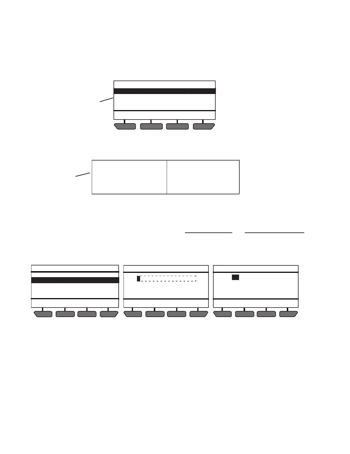
Figure 5.4 Setting Configurations
2. Eleven Configuration sub-menus will be available. To scroll through the Configuration sub-menu list, press
the ▲ or ▼ key. The sub-menus will highlight as the list is scrolled. The available sub-menus include:
3. With the desired sub-menu highlighted, press the “=” key. The individual Configurations within the sub-menu
will display. There are two types of Configuration screens, data entry screens and value selection screens.
4. Data entry screens are displayed for the UNIT MODEL #, TRAILER ID #, UNIT SERIAL #, SET DATE &
TIME and SET NEW HOURS (in a replacement main microprocessor) Configurations. To change a data
entry screen press the “=” key with the configuration highlighted.
5. A data entry screen will be displayed with the entry points in a horizontal row of “fields”. The first selection
“field” will be highlighted. Press the “=” key to enter the field then press the ▲ or ▼ key to scroll through the
available selections.
• When setting a number, the numbers 1 to 9 and the letters A to Z will be displayed.
• When entering the date & time the day, month, year, hour or minute will be displayed. The system uses a
24 hour clock. Hours 00 to 11 are AM and hours 12 to 23 are PM.
• With the desired selection in the field, press the “=” key to save the field entry.
6. Press the ▲ or ▼ key to move to the next field or to the desired field. Press the “=” key to enter the field then
7. Press the ▲ or ▼ key to scroll through the available selections. With the desired selection in the field, press
the “=” key to save the field entry.
8. Continue as above to enter additional field changes as required.
BACK
EXIT
UNIT IDENTIFICATION
SETPOINT(S) & RANGE LOCK
START-STOP SETTINGS
INTELLISET & PRODUCTSHIELD
CONFIGURATION SETTINGS (1 OF 11)
2 & 3
Refer to Table 5ï1, page 5ï16, for information on the settings in each
sub-menu and resultant System actions.
UNIT IDENTIFICATION
SETPOINT(S) & RANGE LOCK
START-STOP SETTINGS
INTELLISET & PRODUCT SHIELD
ENGINE SETTINGS
ALARM SETTINGS
HOUR METERS
REMOTE SENSORS
OTHER SETTINGS
RAIL SETTINGS
AUTO FRESH AIR SETTINGS
END OF LIST
2
BACK EXIT
UNIT IDENTIFICATION (2 OF 4)
UNIT MODEL #:
TRAILER ID #:
UNIT SERIAL #:
SET DATA & TIME:
NDK537N6LF0
MY TRAILER #1
NAR91108766
MAY 23 2013 08:27
CANCEL SAVE
INSTRUCTIONS
Press UP/DOWN To Select Field
EQUAL to Modify Field
SET #
CANCEL SAVE
28 FEB 2011 09:42
INSTRUCTIONS
Press UP/DOWN To Select Field
EQUAL to Modify Field
SET DATE AND TIME

 Loading...

