8–33 62-11640
8.9 ELECTRICAL SYSTEM COMPONENT SER-
VICE
Procedures for servicing or maintaining the electrical
system components are provided in the following sub-
paragraphs.
NOTE
When any module is replaced, software
should be upgraded before switching the
unit on. This will ensure software compatibil-
ity of all modules.
8.9.1 Main Microprocessor Module (MM)
For complete Main Microprocessor Module replace-
ment instructions refer to Section 5.5.2
8.9.2 Power Control Module (PCM)
NOTE
The buzzer, buzzer harness, fuses, door, door
seal, hinge pin, door screw (with retainer) and
relays may be purchased separately and do
not require complete module replacement.
1. Disconnect main power leads at battery.
2. Open Power Control module door. Loosen &
remove stud-post terminal nuts (brass) at termi-
nals BAT+ (6, Figure 8.29); BAT– (7); ALT+ (5)
& EPH (3).
3. Remove nuts holding plastic bushings (4) &
leave hanging on wire.
4. Lift the 4 cable terminals up & off stud-posts.
Remove loose nuts, slide plastic bushings &
cables/terminals out of mounting hole in box.
5. Unlock tab on 35 pin connector (2) & remove
connector.
6. Remove the four fasteners (1) mounting Power
Control module to unit frame & remove module
from unit
7. Follow steps above in reverse order to install
new Power Control Module. Torque:
• fasteners mounting module to frame (1) to 38
to 58 inch/lbs (4.3 to 6.6 Nm)
• M6 terminal nuts (3 & 7) to 30 to 40 inch/lbs
(3.4 to 4.5 Nm)
• M8 terminal nuts (5 & 6) to 60 to 80 inch/lbs
(6.8 to 9.0 Nm). See Figure 2.5.
8. Note a component legend sticker is to be
located inside the PCM door. Install the correct
sticker (packaged with the replacement PCM)
for this unit inside the replacement PCM. The
replacement PCM is populated at the factory
with the standard fuses and relays. Additional
fuses and relays may be required for this appli-
cation (refer to Figure 2.5) transfer the required
fuses and relays from the original PCM to the
replacement PCM as required.
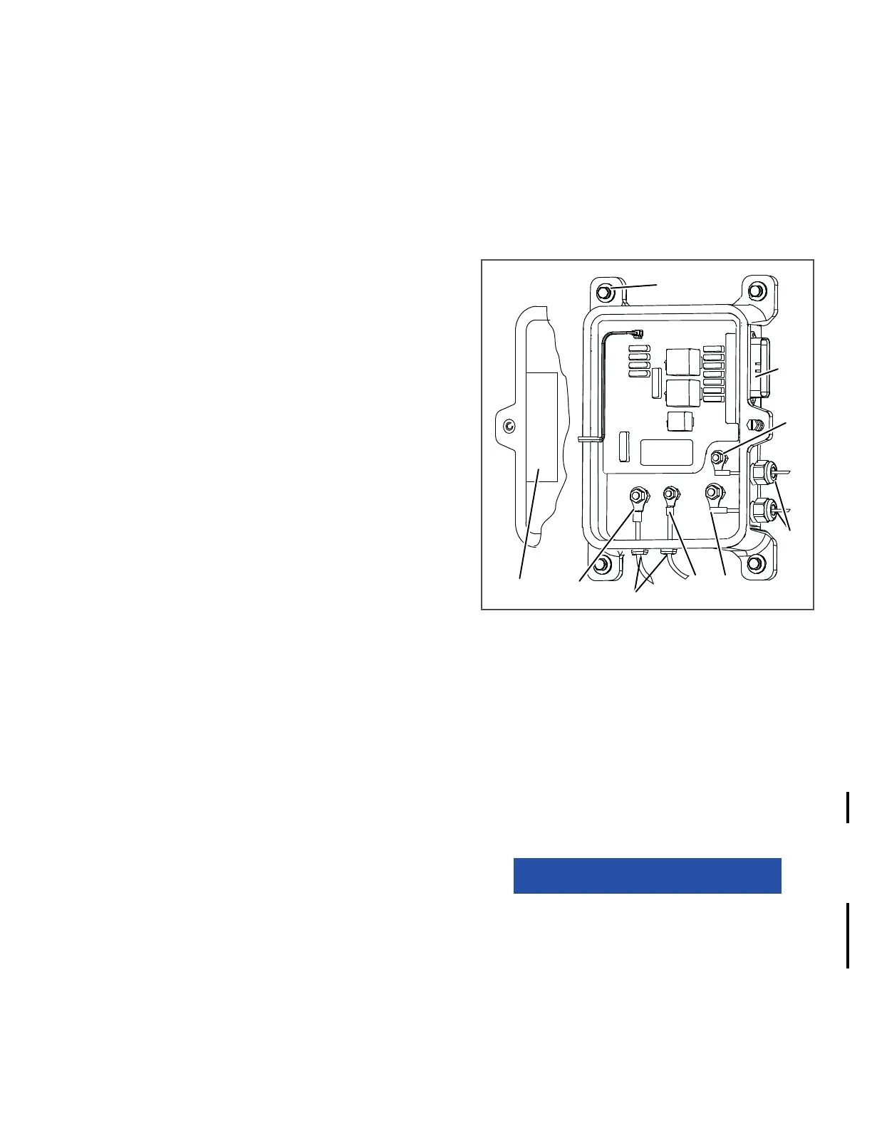
Figure 8.29 Power Control Module
1. Mounting Fasteners
2. 35 Pin Connector
3. Engine Preheat Terminal (EPH)
4. Plastic Bushings
5. Alternator Positive Terminal (ALT +)
6. Battery Negative Terminal (BAT-)
7. Battery Positive Terminal (BAT +)
8. Door Mounted Legend Sticker
- - - - -
9. Make sure the latest software has been loaded
to ensure all modules are compatible, refer to
Section 5.3.4.
NOTICE
When a module is replaced, software
should be upgraded before switching the
unit on. This will ensure software com-
patibility of all modules.
10. Start unit and run Pretrip to check operation.
1
2
3
4
5
6
4
7
8
Change 09/14

 Loading...

