8–25 62-11640
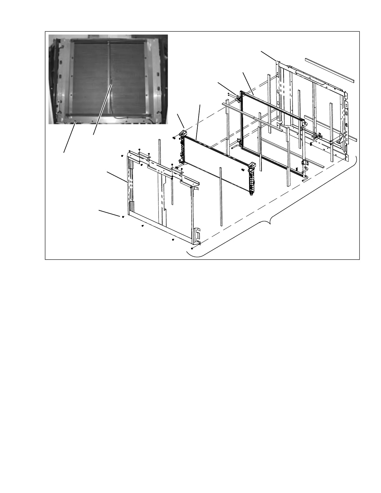
Figure 8.20 Condenser/Radiator Assembly
1. Condenser/Radiator Assembly
2. Condenser Frame
3. Condenser Coil
4. Radiator
5. Radiator Frame
6. Ambient Air Temperature Sensor (ATT)\
7. Condenser/Radiator Assembly Mounting
Bolts
8. Radiator Frame Mounting Bolts
9. Radiator Mounting Brackets
10. Condenser Coil Mounting Brackets
- - - - -
8.8.3 Filter-Drier
a. Check Filter-Drier
The unit must be running in cool for this test. Check for
a restricted or plugged filter-drier by feeling the liquid
line inlet and outlet connections of the drier cartridge.
If the outlet side feels cooler than the inlet side, then
the filter-drier should be replaced.
b. Replace Filter-Drier
1. Pump down the low side. Refer to Section 8.6.2.
2. Remove bracket, loosen the inlet connection to
relieve any remaining pressure then remove
drier.
3. Procure new O-rings. Lubricate the O-rings,
back side of sleeves and coupling nuts. Using a
backup wrench at each connection torque 30 to
38 ft/lbs (40.7 to 51.5 Nm).
4. Leak check, evacuate & dehydrate, and charge
system as required. Refer to Section 8.6.2,
Section 8.6.3 & Section 8.6.4.
8.8.4 Replacing Receiver Sight Glass Or Fus-
ible Plug
1. Remove the refrigerant charge. Refer to Sec-
tion 8.6.2.
2. Loosen the sight glass or fusible plug to relieve
any remaining pressure. Remove and discard
glass or plug.
3. Using new o-ring, install component. Torque the
sight glass to 15 to 25 ft/lbs (20.3 to 33.9 Nm).
Torque the fusible plug to 48 to 96 inch/lbs (5.4
to 10.8 Nm).
4. Leak check, evacuate & dehydrate, and charge
system as required. Refer to Section 8.6.2,
Section 8.6.3 & Section 8.6.4.
1
2
3
4
5
6
77
8
9
10

 Loading...

