62-11640 8–30
8.8.8 Liquid Injection Solenoid Valve
a. Replacing the Coil:
NOTE
The coil may be replaced without removing
the refrigerant.
1. Ensure the unit will not start automatically by
disabling any two way communication and plac-
ing the STOP/RUN-OFF switch in the OFF posi-
tion. Disconnect the high voltage source and
lockout/tagout the receptacle.
2. Disconnect coil connector.
3. Remove locking nut, upper O−ring, threaded
collar coil and lower O−ring (See Figure 8.26).
4. Verify coil type, voltage and frequency of old
and new coil. This information appears on the
coil housing.
5. Ensure upper and lower O−rings are installed on
top and bottom of coil and tighten locking nut to
1.2 to 1.4 Nm (10 to 18 inch−pounds).
b. Repairing the Valve:
1. Pump down the low side. Refer to Section
8.6.2.
2. Remove the armature tube, taking care the
armature and spring do not drop out.
3. Ensure the spring is properly seated in the
armature and install into the armature tube.
4. Install a new internal O−ring into the valve body
and then reinstall the enclosing tube with arma-
ture and spring.
c. Replacing the Valve:
1. To replace a valve, pump down the low side.
Refer to Section 8.6.2.
2. Ensure the unit will not start automatically by
disabling any two way communication and plac-
ing the STOP/RUN-OFF switch in the OFF posi-
tion. Disconnect the high voltage source and
lockout/tagout the receptacle.
3. Remove coil, refer to “Replacing the Coil”
above.
4. Unbraze valve from unit and braze new valve in
place. Wrap valve in wet rag and point flame
away from valve during brazing operation.
5. Install coil, refer to “Replacing the Coil” above.
Leak check, evacuate the unit and charge in
accordance with Section 8.6.
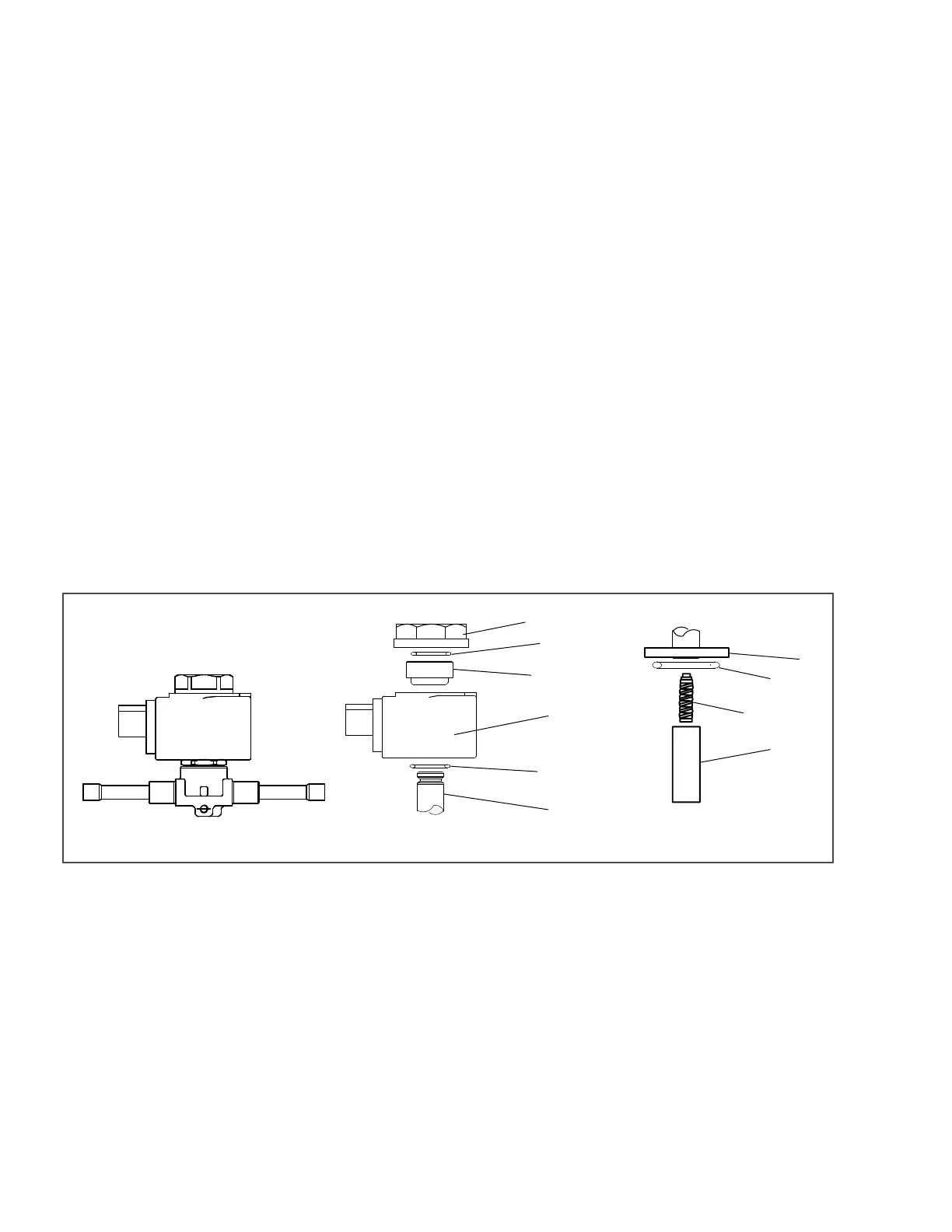
Figure 8.26 Solenoid Valve
1. Locking Nut
2. Upper O−Ring
3. Threaded Collar
4. Coil
5. Lower O−Ring
6. Armature Tube
7. Internal O−Ring
8. Spring
9. Armature
- - - - -
8.8.9 High Pressure Switch
a. Replacing High Pressure Switch
1. Pump down the compressor (Section 8.6.2).
2. Disconnect wiring from switch, and remove
switch.
3. Install switch after verifying switch settings.
(Refer to following step b.)
4. Leak check, evacuate & dehydrate, and charge
system as required. Refer to Section 8.6.2,
Section 8.6.3 & Section 8.6.4.
COIL ASSEMBLY INTERNAL COMPONENTSLIQUID INJECTION VALVE
1
2
3
4
5
6
6
7
8
9

 Loading...

