Wiring the Carrier® ChillerVu™ for power
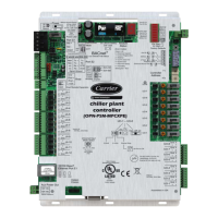
Carrier® ChillerVu™
(OPN-PSM-MPCXPE) Carrier Proprietary and Confidential CARRIER CORPORATION ©2017
Installation and Start-up Guide 8 All rights reserved
Do not apply line voltage (mains voltage) to the controller's ports and terminals.
• The Carrier® ChillerVu™ is powered by a Class 2 power source. Take appropriate isolation measures when
mounting it in a control panel where non-Class 2 circuits are present.
• Carrier controllers can share a power supply as long as you:
• Maintain the same polarity.
○ Use the power supply only for Carrier controllers.
1 Turn off the Carrier® ChillerVu™'s power switch to prevent it from powering up before you can verify the
correct voltage.
2 Remove primary power from the 24 Vac transformer.
3 Pull the screw terminal connector from the controller's power terminals labeled
and
.
4 Connect the transformer wires to the screw terminal connector.
5 Apply primary power to the transformer.
6 Measure the voltage at the controller's power screw terminal connector to verify that the voltage is within the
operating range of 21.6 - 26.4 Vac.
7 Insert the screw terminal connector into the controller's power terminals.
8 Turn on the Carrier® ChillerVu™'s power switch.
9 Verify that the Power LED is on and the Run LED is blinking.
Wiring the Carrier® ChillerVu™ for power