Wiring inputs and outputs
Carrier® ChillerVu™
(OPN-PSM-MPCXPE) Carrier Proprietary and Confidential CARRIER CORPORATION ©2017
Installation and Start-up Guide 18 All rights reserved
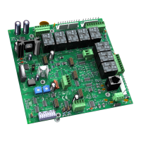
The Carrier® ChillerVu™ and expanders have universal outputs that you can use as binary outputs or analog
outputs. The outputs support:
• driving external 24 Vdc relays
• 0-10 Vdc devices
• 0-20 mA devices
Binary outputs are powered, 24 Vdc channels. Dry contact binary outputs are not supported in
this product line. Do NOT apply 24 Vac to these universal outputs.
Resistance to ground must be...
0–10 Vdc device 500 Ohms minimum
0–20 mA device 800 Ohms maximum
• The device must share the same ground as the controller.
• The total output current from all outputs and the
connection must not exceed:
500 mA at 115°F
300 mA at 140°F
For temperatures above 115°F, use the following equation to calculate the total current at 8 mA per degree:
500mA - ((max. expected temp. - 115°F) * 8mA)
To wire inputs and outputs
Do not apply line voltage (mains voltage) to the controller's ports and terminals.
The following applies to the inputs and outputs on the Carrier® ChillerVu™ and expanders.
1 Verify that the Carrier® ChillerVu™'s power and communications connections work properly.
2 Turn
the Carrier® ChillerVu™'s power.
3 Connect the input wiring to the screw terminals on the controller or expander. See figure below.
○ Connect the shield wire to the
terminal with the ground wire.
○ For a loop-powered 4-20 mA sensor, wire the sensor's positive terminal to the
terminal on the Carrier®
ChillerVu™'s
connector. Wire the sensor's negative terminal to an input's
terminal.
 Loading...
