Check of drive belt tensioning
75806
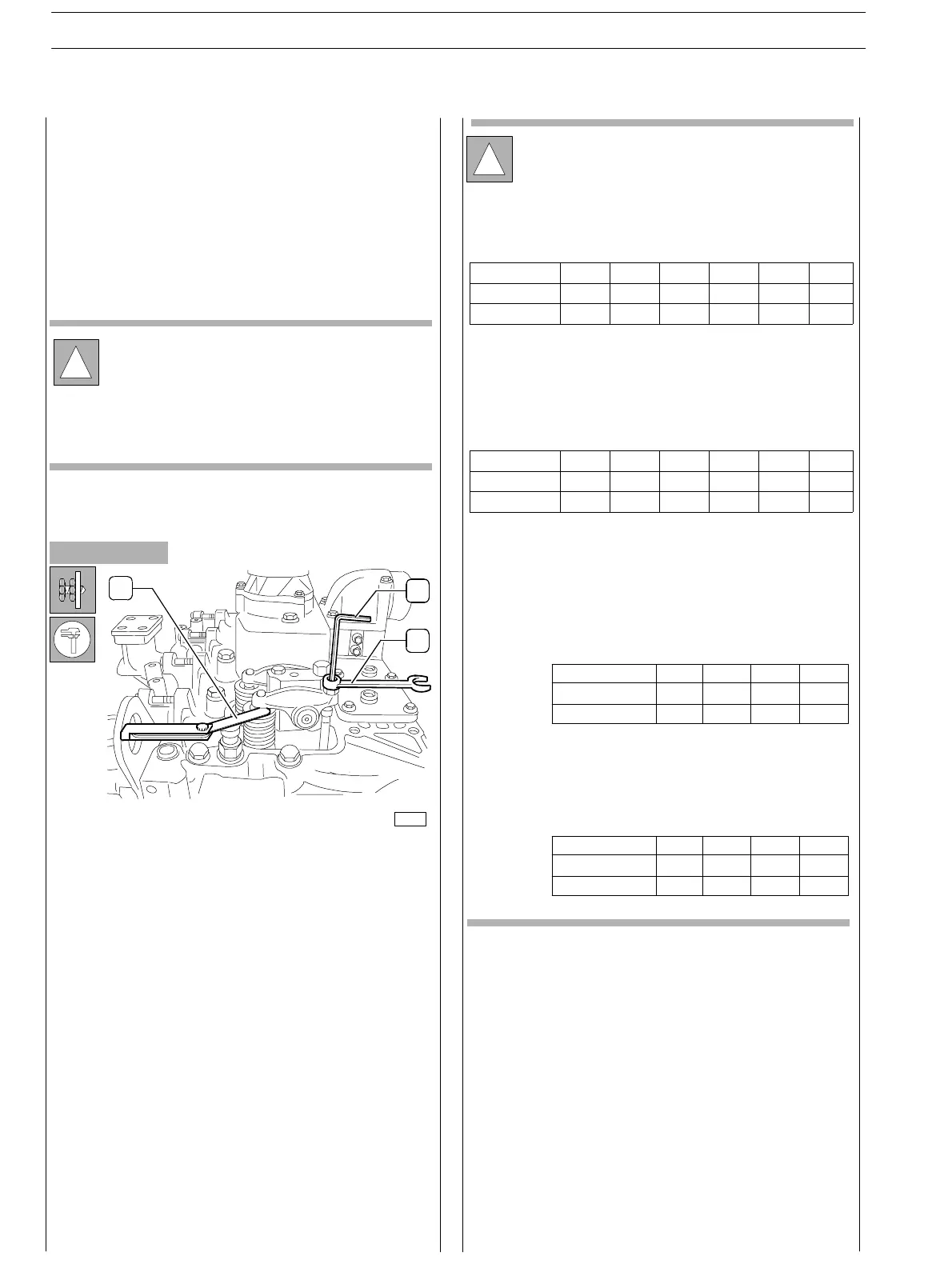
Adjust clear ance between rockers and valves using setscrew
wrench (1), box wrench (3) and feeler gauge (2).
Working clearance shall be as follows:
− intake valves 0.30 ± 0.05 mm
− exhaust valves 0.55 ± 0.05 mm.
!
In order to more quickly perform the operating clear-
ance adjustment for rocker arms — valves, proceed as
follows:
rotate the drive shaft, balance cylinder 1 valves and
adjust the valves marked by the asterisk as shown in
the table:
Rotate the drive shaft of 360 deg., balance cylinder 6
valves and adjust the valves marked by the asterisk as
showninthetable:
Engine with 4 cylinder: rotate the drive shaft, balance
cylinder 1 valves and adjust the valves marked b y the
asterisk as shown in the table:
Rotate the drive shaft of 360 deg., balance cylinder 4
valves and adjust the valves marked by the asterisk as
showninthetable:
cylinder n.
intake
exhaust
1
234
−
*
**
*
−
−−
cylinder n.
intake
exhaust
1
234
−
*
**
*
−
−
−
Check and setting of tappet clearance
Figure 235
2
1
3
Some applications are equipped with an automatic tensioner
that provides correcting belt tensioning.
Check of belt’s tear and wear status
Carefully verify the belt’s surface in order to detect any sign of
incision, crack, excessive wear in cor r espondence of toothing;
check end and surface grinding.
!
Danger: if the engine is switched off but is still hot, un-
expected motion of the belt may occur.
Wait for engine temperature cooling as a precaution
in order to avoid serious danger injury.
SECTION 3 − DUTY − INDUSTRIAL APPLIC ATION
96
ENGINES
ED. FEBUARY 2003
cylinder n. 1 2 3 4 5 6
intake * * − * − −
exhaust * − * − * −
cylinder n. 1 2 3 4 5 6
intake − − * − * *
exhaust − * − * − *