70194
70195
70196
Figure 50
Figure 51
Figure 52
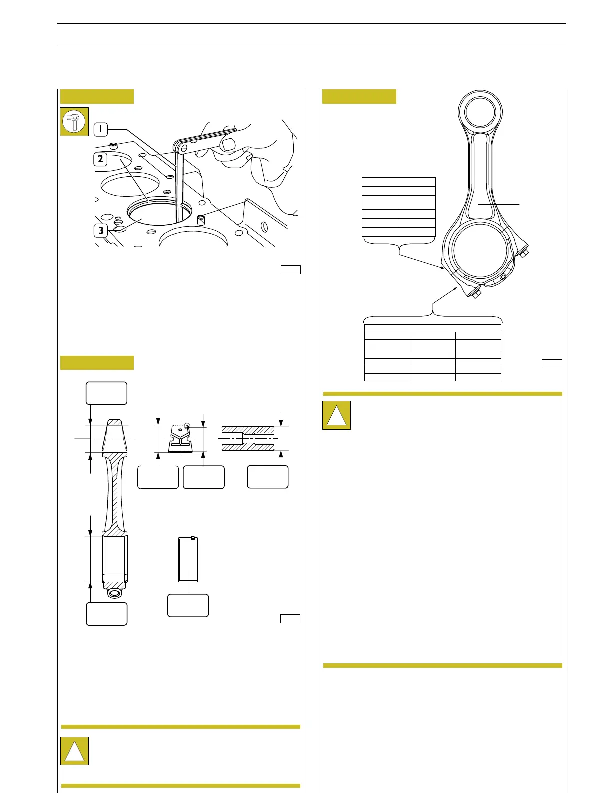
Use feeler gauge (1) to measure the clearance between the
ends of the split rings (2) fitted into the cylinder barrel (3).
MAIN DATA FOR CONNECTING ROD, BUSH,
PISTON PIN AND HALF BEARINGS
* Value for inside diameter to be obtained after driving in
connecting rod small end and grinding.
** Value not measurable in released condition
Bushes
Check that the bush in the connecting rod small end is free
from scoring or seizing and that it is not loosen. Otherwise
replace.
Removal and refitting shall be performed using the proper
beater.
When refitting take care to make coincide the oil holes set
on the bush with those set on the connecting rod small end.
Grind the bush to obtain the specified diameter.
Connecting rods
!
Every connecting rod is marked as follows:
On body and cap with a number showing their
coupling and the corresponding cylinder.
In case of replacement it is therefore necessary
to mark the new connecting rod with the same
numbers of the replaced one.
On body with a letter showing the weight of the
connecting rod assembled at production:
V, 1820 to 1860 (yellow marking);
W, 1861 to 1900 (green marking);
X, 1901 to 1940 (blue marking);
Spare connecting rods are of the W class with green
marking *.
Material removal is not allowed.
*
*
*
*
*
*
!
The surface of connecting rod and rod cap are
knurled to ensure better coupling.
Therefore, it is recommended not to smooth the
knurls.
SECTION 4 – OVERHAUL AND TECHNICAL SPECIFICATION
ENGINES
25
ED. FEBRUARY 2003
CONNECTING ROD BODY
1234 W
CONNECTING
ROD No.
WEIGHT
0001 V
W
9999 X
CONNECTING ROD CAP
1234 A 123
CONNECTING
ROD No.
YEAR DAY
0001 A 1998 001
B 1999
9999 C 2000 366
D 2001
40.987
41.013
40.987
41.013
38.019
38.033
38.000
38.006
1.955
1.968
72.987
73.013