70512
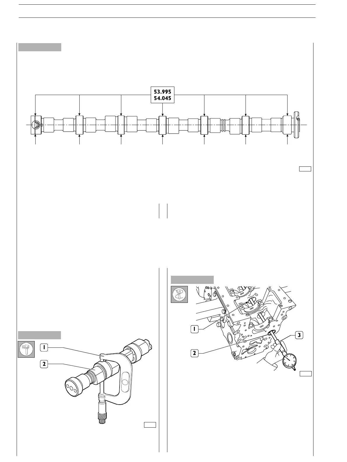
Figure 13
MAIN DATA ABOUT CAMS HAFT PINS (6 CYL.)
Camshaft pin and cam surfaces shall be absolutely smooth;
if they show any traces of seizing or scoring replace the
camshaft and the bushes.
70171
70172
Figure 14
Figure 15
Check camshaft (2) pin diameter using micrometer (1) on
two perpendicular axes.
Camshaft bushes (2) shall be pressed into their housings.
Internal surfaces must not show seizing or wear.
Use bore dial gauge (3) to measure camshaft front and rear
bush (2) and intermediate housing (1) diameter.
Measurements shall be performed on two perpendicular
axes.
BUSHESChecking cam lift and pin alignment
Set the camshaft on the tailstock and usin g a 1/100 gauge set
on the central support, check whether the alignment error
is not exceeding 0.04 mm, otherwise replace the camshaft.
Check cam lift; found values shall be: 6.045 mm for exhaust
cams and 7.582 mm for intake cams, in case of different values
replace the camshaft.
SECTION 4 − OVERHAUL AND TECHNICAL SPECIFICATIONS
14
E NG I NE S
ED. FEBUARY 2003