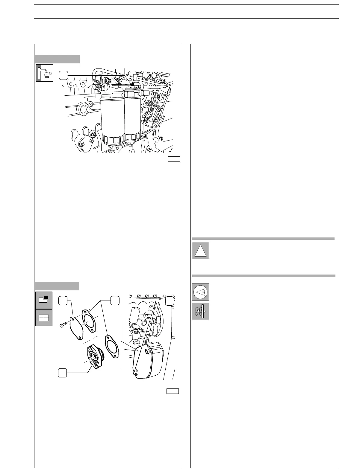
Figure 213
In case any operation has been executed on the components
of the feed circuit, it is necessary to execute bleeding of air
within the system.
Loosen the bleeder vent screws (1) on the fuel filter
supports.
Switch starter revolution on, activating the priming
pump and driving fuel delivery to the filters.
Continue executing this operation until when fuel drains
from the bleeder vent screws, then tighten the screws.
Vary out the assembly fitting the power take-off in its
housing, providing new gasket and checking the sprocket
gear meshing.
Assemble cover and gasket and tighten the screws to the
prescribed couple.
Figure 214
!
The following tests shall be made after engine
assembly to the vehicle.
Preventively check that the liquid levels have been
correctly restored.
Feed system bleed procedure
Where designed, there is a power take- o ff a ble to transmit
motion to different auxiliary parts.
Disassembly of such mechanism shall be executed as
following:
Loosen the two screws (3) and after having removed the
cover (1) with a specially provided extractor, withdraw
The power take-off (2).
The two gaskets (4) shall be replaced in phase of
reassemble.
76137
Checks and controls
There is no water bleeding from the manifolds
connecting engine cooling circuit pipelines and cabin
internal heating, eventually providing to further tighten
the locking rings.
Carefully check the fuel connection pipes to the
respective unions.
There is no oil leakage from the lubrication circuit of the
various pipelines connecting cover and.
Cylinder head, oil pan and bearing, oil filter and heat
exchanger as well as relating housings.
There is no fuel leakage from fuel pipelines.
There is no blowby from pneumatic pipes (if provided).
Verify correct working of the lighting leds of the
dashboard containing the tools as well as of the
equipment that was disconnected during engine
disconnection.
Check and blow by with care the engine cooling system,
carrying out frequent drainage.
Start the engine, let it run at revolution regimen
slightly higher than idling and wait that the cooling
liquid temperature reaches the value enabling
thermostat opening, then check that:
76140
SECTION 3
–
DUTY
–
INDUSTRIAL APPLICATION ENG INES
69
ED. FEBUARY 2003
.
❏
❏
❏
❏
❏
❏
❏
❏
❏
❏
❏
❏
❏
❏
❏
1
2
3
4
Power take-off disassembly and assembly
procedure
1