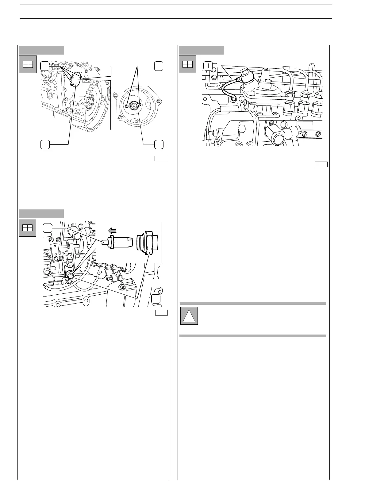
Figure 210
- Assemble the cover (2, Figure 210) including gasket and
tighten the screws (1,Figure210).
- Pull the pin outwards setting the camshaft gear free.
-
Remove the 380000988 tool locking flywheel rotation;
place the starter in its housing.
- Connect all pipelines (from pumping elements to
injectors, bleeding recovery pipes from in jec t ors to
pump, LDA pipeline (1) and feed provided by priming
pump and lubrication pipelines).
- Connect electrical switch devices to engine stop.
Figure 211
Figure 212
1
23
4
75715
- On th e timing side, throughout the specially appointed
port, fit the washer and screw up the fixing nut (3) to the
pump shaft. Lock the nut to the 90−95 Nm c o uple.
!
In case pump removal has been carried out while the
engine was assembled, connect acceleration cable.
76134
- Remove th e hexagon shaped cap (1) from the speed
gauge box and with draw locking pin (2) from the
camshaft.
- Tur n th e locking pin (2) upsidedown an d place it in its
housing: this operation enables free rotation of the
pump’ s camshaft.
- Assemble the hexagon shaped cap (1) to the speed
gauge box.
76139
1
2
SECTION 3 − DUTY − INDUSTRIAL APPLICATION
68
E NG I NE S
ED. FEBUARY 2003
zs