32620
16552
32619
18857
41104
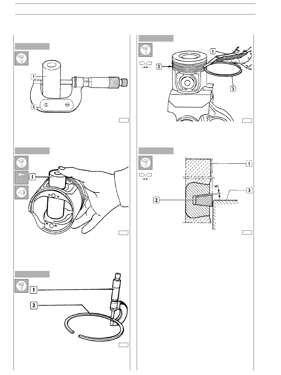
Figure 45
Figure 46
Figure 47
Figure 48
Figure 49
To measure the piston pin (1) diameter use the micrometer
(2).
Conditions for proper pin−piston coupling
Lubricate the pin (1) and its seat on piston hubs with engine
oil; the pin shall be fitted into the piston with a slight finger
pressure and shall not be withdrawn by gravity.
Use a micrometer (1) to check split ring (2) thickness.
Check the clearance between the sealing rings (3) of the 2
nd
and 3
rd
slot and the relevant housings on the piston (2), using
a feeler gauge (1).
DIAGRAM FOR MEASURING THE CLEARANCE X
BETWEEN THE FIRST PISTON SLOT AND THE
TRAPEZOIDAL RING
Since the fir st sealing ring section is trapezoidal, the clearance
between the slot and th e r in g shall be measured as follows:
make the piston (1) protrude from the engine block so that
the ring (2) protrudes half−way from the c ylinder barrel (3).
In this position, use a feeler gauge to check the clearance (X)
between ring and slot: found value shall be the specified one .
Piston pins
Split rings
SECTION 4 − OVERHAUL AND TECHNICAL SPECIFICATIONS
24
E NG I NE S
ED. FEBUARY 2003