70163
70165
70164
70166
70167
Figure 6
Figure 7
Figure 8
Figure 9
Figure 10
Remove the screws (1) and disconnect camshaft (3) retaining
plate (2).
Withdraw carefully the camshaft (1) from the en gin e block.
Withdr aw the tappets (1) from the engine block.
Once engine is disassembled, clean accurately the
cylin der−bloc k assembly.
Use the proper rings to handle the cylinder unit.
The engine block shall not show c racks.
Check operating plug conditions and replace them in case of
uncertain seal or if rusted.
Inspect cylinder barrel su rfaces; th ey shall be free from seizin g,
scores, ovalisation, taper or excessive wear.
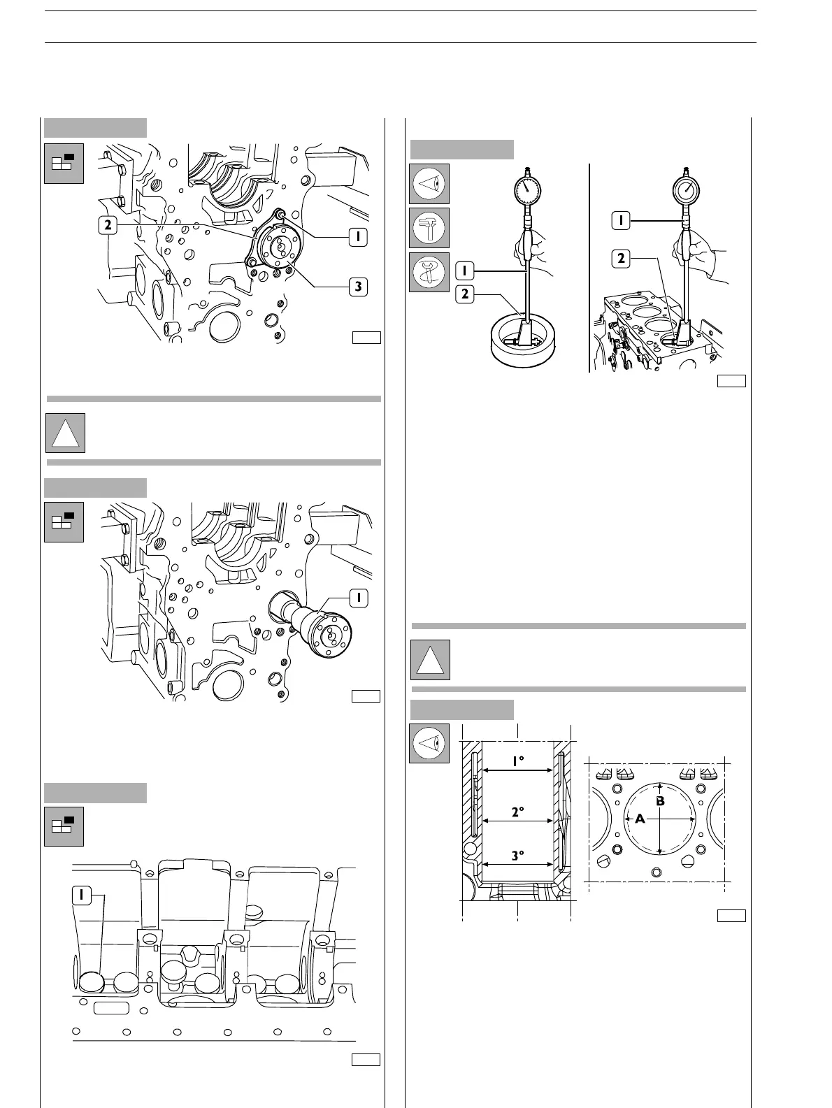
Inspection of cylinder barrel bore to check ovalisation, taper
and wear shall be performed using a bore dial gauge
(I) fitted with the dial gauge previously set to zero
on the ring gauge (2) of t he cylinder barrel diameter.
Measurements shall be performed on each cylinder, at three
different heights in the barrel and on two planes
perpendicular with each other: on e parallel to t h e
longitudinal axis of the engine (A), and the oth er
perpendicular (B). Maximum wear is usually found on plane
(B) in correspondence with the first measurement.
Should ovalisation, taper or wear be found, bore an d grind
the cylinder barrels. Cylinder barrel regrinding sh all be
performed according to the spare piston diameter oversized
by 0.5 mm and to the specified assembling clearance.
!
Take note of plate (2) assembling position.
REPAIR OPERATIONS
CYLINDER UNIT
Checks and measurements
!
Should the r ing gauge be n o t available, use a
micrometer for zero−setting.
s
SECTION 4 − OVERHAUL AND TECHNICAL SPECIFICATIONS
12
E NG I NE S
ED. FEBUARY 2003
zs