70184
70185
70187
Figure 31
Figure 32
Figure 33
Figure 34
Refit the output shaft (2).
Check the backlash between output shaft main journals and
the relevant bearings as follows:
Tighten the pre−lubric ated screws (1) in the following three
succ essive stages:
- 1
st
stage , with dynamometric wrench to 50 ± 6 Nm.
- 2
nd
stage , with dynamometric wrench to 80 ± 6 Nm.
!
Refit the main bearings that have not been replaced,
in the same position fou nd at removal.
Fitting main bearings
!
Do not try to adapt the bearings.
Main bearings (1) are supplied spare with 0.250 — 0.500 mm
undersize on the internal diameter.
Clean accurat ely the main half bearings (1) having the
lubricating hole and fit them into their housings.
The second last main half bearing (1) is fitted w ith shoulder
half rings.
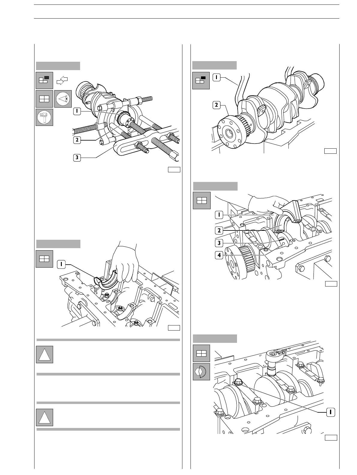
Check that gear toothing (1) is not damaged or worn,
otherwiseremoveitusingtheproperpuller(3).
When fitting the new gear, heat it to 180°C for 10 minutes
in an oven and then key it to the output shaft.
Finding journal clearance
Figure 35
- clean accurately the parts and remove any trace of oil;
- position a piece of c alibrated wire (3) on the ou t put sh aft
pins (4) so that it is parallel to the longitu dinal axis;
- fit caps (1), including t he half bearings (2) on the relevan t
supports.
70186
70161
Replacing oil pump control gear
SECTION 4 − OVERHAUL AND TECHNICAL SPECIFICATIONS E NG I NE S
21
ED. FEBUARY 2003