70179
70180
70182
70181
Figure 23
Figure 24
Figure 25
Figure 26
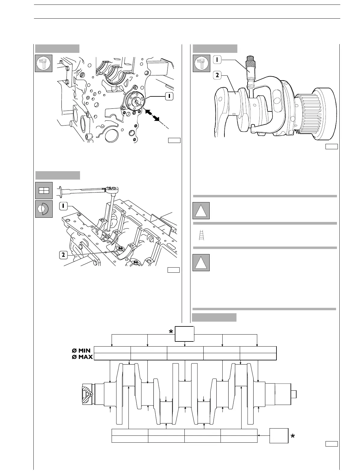
Ch ec k c amsh aft en d float (1).
It shall be 0.23± 0.13 mm.
Fit n ozzles (2) and tigh ten the fasten ing screws (1) to the
spec ified t orqu e .
Gr in d jou r n als an d c r an kpin s if seiz in g, sc o r in g or exc essive
ovalisation are found. Before gr inding the pins (2) measure
them with a micrometer (1) to decide the final diameter to
whic h the pins are to be ground.
!
It is recommended to inser t the found values in the
pr o pe r t a bl e .
SeeFigure26.
Un der size c lasses are:
!
Jour nals and c r ankpins shall alway s be ground to the
same u n der size c lass.
Jour nals and c r ankpins under size shall be mar ked on
thesideofthecrankarmNo.1.
For under sized c r ankpins: letter M
For u n der sized jou r n als: letter B
For under sized crankpins and journals: letters MB
FILL THIS TABLE WITH OUTPUT SHAFT JOURNAL AND CRANKPIN MEASURED VALUES
*Rated value
82.99
83.01
68.98
69.01
SECTION 4 − OVERHAUL AND TECHNICAL SPECIFICATIONS
E NG I NE S
17
ED. FEBUARY 2003
OUTPUT SHAFT
Measuring journals and crankpins