70207
70208
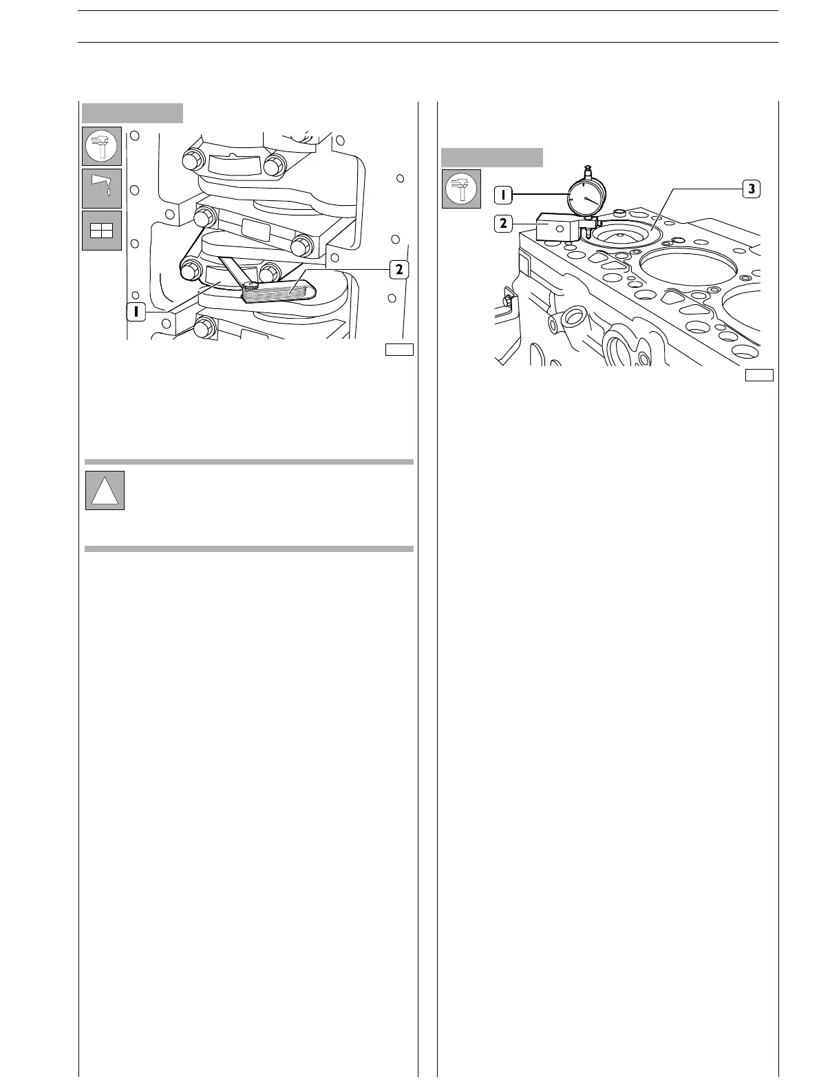
Figure 68
Figure 67
If a different clearance value is found, replace the half bearings
and repeat the check.
Once the specified clearance has been obtained, lubricate
the main half bearings and fit them by tightening the
connecting rod cap fastening screws to the specified torque.
Once connecting rod−piston assemblies refitting is over, u se
dial gauge (I) fitted with base (2) to check piston (3)
protrusion at T.D.C. with respect to the top of the engine
oftheengineblock.
Protru sion shall be 0.28 to 0.42 mm.
!
Before the final fitting of the connecting rod cap
fastening screws, check that their diameter
measured at the centre of the thread length is not
<0.1 mm than the diameter measured at approx. 10
mm from screw end.
Check manually that the connecting rods (1) are sliding
axially on the output shaft pins and that their end float,
measured with feeler gauge (2) is 0.250 to 0.275 mm.
Checking piston protrusion
SECTION 4 − OVERHAUL AND TECHNICAL SPECIFICATIONS E NG I NE S
29
ED. FEBUARY 2003