Figure 69
Intake (1) and exhaust (2) valves have heads with different
diameter.
!
Should cylinder head valves be not replaced, number
them before removing in order to refit them in the
same position.
A = int ake side
CYLINDER HEAD
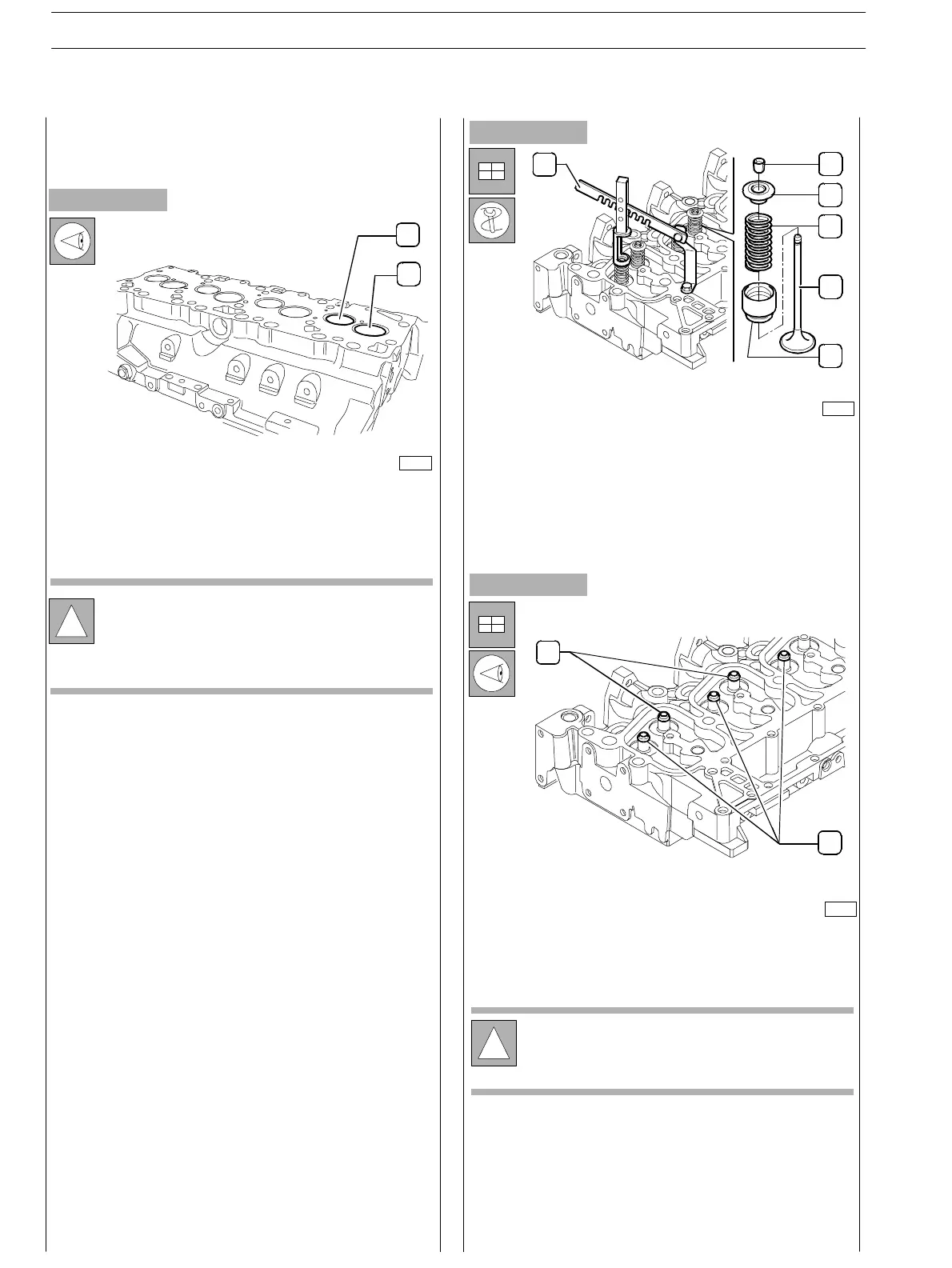
Removing the valves
Valve removal shall be performed using acceptable tools (I)
and pressing the cap (3) so that when compressing the
springs (4) the cotters (2) can be removed. Then remove the
cap (3) and the springs (4).
Repeat this operation for all the valves.
Overturn the cylinder head and withdraw the valves (5).
75751
75752
Figure 70
Figure 71
!
Sealing rings (1) for intake valves are yellow.
Sealing rings (2) for exhaust valves are green.
Remove sealing rin gs (1 and 2) from t he valve guide.
1
2
3
4
5
6
2
1
75750
1
2
A
SECTION 4 − OVERHAUL AND TECHNICAL SPECIFICATIONS
30
E NG I NE S
ED. FEBUARY 2003