72705
70199
32613
70200
70201
Figure 57
Figure 58
Figure 59
Figure 60
Figure 61
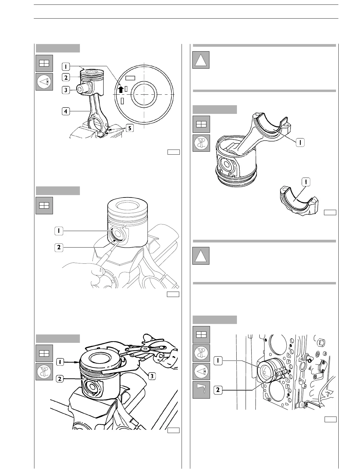
Connect piston (2) to connecting rod (4) with pin (3) so that
the reference arrow (1) for fitting the piston (2) into the
cylinder barrel and the numbers (5) mar ked on the
connecting rod (5) are read as shown in the figure.
Position the piston (1) on the connecting rod according to
the diagram shown in the figure, fit th e pin (3) and stop it by
the split rings (2).
Fitting split rings
Use acceptable tools (3) to fit the split rings (I) on the
piston (2).
Split rings shall be fitted with th e marking “TOP” facin g
upwards and their openings shall be displaced with each
other by 120°.
Fit half bearin gs (1) on conn ec t ing rod and cap.
Lubricate accurately the pistons, in c lu ding the split rin gs and
the cylinder barrel inside.
Use acceptable tools (2) to fit the connecting rod-piston
assembly (1) in t o the c ylinder barrels and check the following:
- the number of each connecting rod shall correspond to
the cap coupling number.
!
Split rings are su pplied spare with the following sizes:
− standard, yellow marking;
− 0.5 mm oversize, yellow/green markin g;
Fitting connecting rod−piston assembly into
cylinder barrels
!
Refit the main bearings that have not been replaced,
in the same position fou nd at removal.
Do not try to adapt the half bearin gs.
SECTION 4 − OVERHAUL AND TECHNICAL SPECIFICATIONS E NG I NE S
27
ED. FEBUARY 2003