70159
70158
70160
70161
70162
Figure 1
Figure 2
Figure 3
Figure 4
The following instructions are prescribed on th e
understanding that the engine has previously been placed on
the rotating bench and that removal of all specific
components of the equipment have been already removed
as well. (See Section 3 of the manual herein).
The section illustrates th erefore all the most import ant
engine overhaul procedures.
The following operations are relating t o t he 4 cylinder s
engine but are analogou sly applicable for the 6 cylinders.
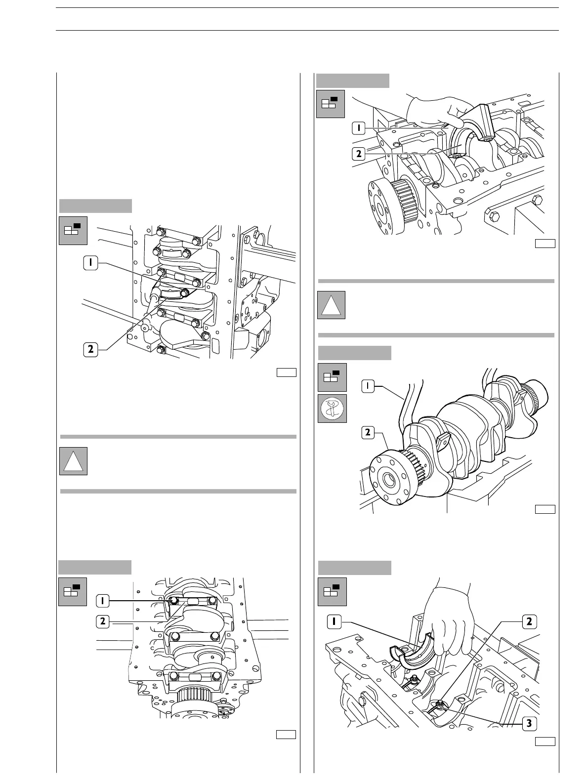
Remove the screws (1) fastening the connecting rod caps (2)
and remove them.
Withdr aw the pistons including the connecting rods from the
top of the engine block.
Remove the screws (1) and the main bearing caps (2).
The second last main bearing cap (1) and the relevan t
support are fitted with shoulder half−bearing (2).
Use acceptable tools (I) and hoist to remove the output
shaft (2) from the block.
Remove the main half−bear ings (1).
Remove the screws (2) and remove the oil nozzles (3).
!
Keep the half−bearings into their housings sin ce in
case of use they shall be fitted in the same position
found at removal.
!
Take note of lower and upper half−bearing
assembling positions since in case of reuse they sh all
be fitted in the same position found at removal.
Figure 5
SECTION 4 − OVERHAUL AND TECHNICAL SPECIFICATIONS E NG I NE S
11
ED. FEBUARY 2003
ENGINE OVERHAUL
ENGINE REMOVAL AT THE BENCH