70202
70203
70204
70205
70206
Figure 62
Figure 63
Figure 64
Figure 65
Figure 66
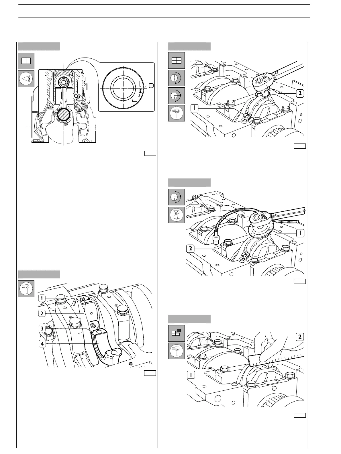
DIAGRAM FOR CONNECTING ROD−PISTON
ASSEMBLY FITTING INTO BARREL
- Split ring openings shall be displaced with each other by
120°;
- connecting rod−piston assemblies shall have the same
weight;
- the ar row marked on the piston crown shall be facing the
front side of the engine block or the slot obtained on the
piston skirt shall be corresponding to the oil nozzle
position.
Finding crankpin clearance
To measure the clearance proceed as follows:
- clean the parts accurately and remove any tr ace of oil;
- setapieceofcalibratedwire(2)ontheoutputshaftpins
(1);
- fit the connecting rod caps (3) with the relevant half
bearings (4).
- Lubricate the screws (1) with engine oil and t hen tighten
them to the specified torque using the dynamometr ic
wrench (2).
-
Apply acceptable tools (I) to the socket wrench and
tigh ten screws (2) of 60° .
- Remove the cap and find the existing clearance by
comparing the calibrated wire width (1) with the scale
onthewireenvelope(2).
α
α
SECTION 4 − OVERHAUL AND TECHNICAL SPECIFICATIONS
28
E NG I NE S
ED. FEBUARY 2003