74195
Figure 6
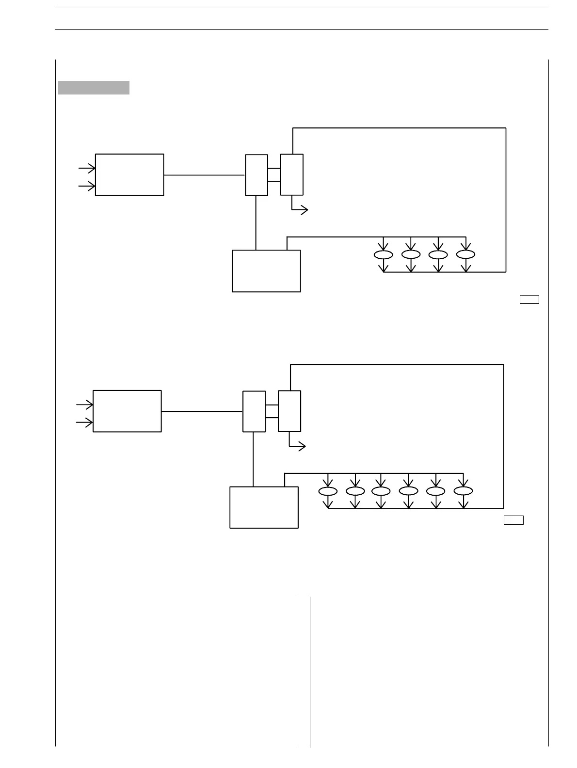
The turbocharger is composed by the following main parts:
one turbine, one transforming valve to regulate the boost
feeding pressure , one main body and one compressor.
Dur ing engine working process, the exhaust emission flow
through the body of the turbine, provoking the turbine disk
wheel’s rotation.
The compressor rotor, being connected by shaft to the
turbine disk wheel, rotates as long as this last one rotates,
compressing the sucked air through the air filter.
The above mentioned air is then cooled by the radiator and
flown through the piston induction collector.
The turbocharger is equipped with a tran sforming valve to
regulate the pressure , that is locat ed on t he exhaust
collector before the turbine and connected by piping to the
induction collector.
It’s duty is to choke the exhaust of the emissions , releasing
part of them directly to the exhaust tube when the boost
feeding pressure, over the compressor, reaches the
prescribed bar value.
The c ooling process and t he lubr ic ation of t h e turbocharger
and of the bear in gs is made by the oil of the engine.
Description
RADI ATO R
AI R FI LTE R
TURBO CHARGE R
EXHAUST
74195
RADIATOR
EXHAUST
TURBOCHARGER
AIR FILTER
E NG I NE S SECTION 1 − GENERAL SPECIFICATIONS 11
ED. FEBUARY 2003
BOOST FEEDING DIAGRAM