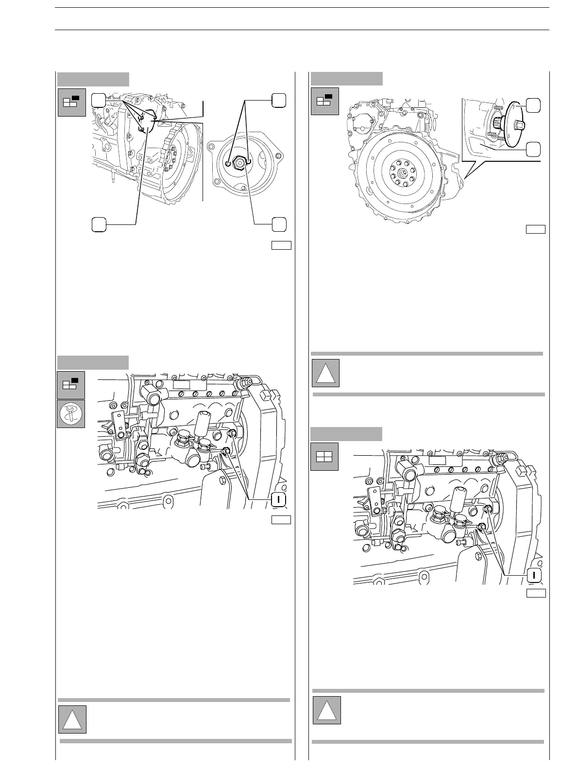
Figure 206
Figure 207
- From the pump side, loosen the fixing nuts (1) without
removing them in order to enable moving the pump
backwards using 380000979 extractor.
-
Assemble the 380000979 extractor throughout the two
threaded ports (4, Figure 206) and withdraw the gear
from the pump shaft.
-
Hold the feed pump using acceptable tools and unscrew
completely the fixing nuts.
- Withdraw the pump from the holding studs together
with the gasket.
Figure 208
- From timing side, remove the cover (2) loosening the
screws (1) in order to have access to the union fixing nut
(3) to the pump driving gear.
- Loosen the fixing nut (3) and remove the relating washer.
When assembling the feed pump to the engine, it is n ecessary
to meet the P.M.S. requirements for the N.I. cylinder.
-
Use the 380000988 tool (2) on the flywheel box (I)
to car ry out flywheel rotation and operate using the pin
as previously described.
Figure 209
!
Hold the pump driving gear to avoid interference or
cr awling during timing gear rotation.
1
23
4
75693
76133
75714
1
2
76133
!
In these conditionsthe pump is pre−set and can be
assembled to the engine further.
-
Hold the feed pump using acceptable tools and assemble
it (pre set pump) to the engine in its housing: insert the
camshaft capule into the port of the pump’s driving gear
(not provided with key).
- Tighten the fixing nuts (1) centering and locking the
pump’s flange within the slot.
!
The gasket removed during pump disassembly shall
not be utilised again.
Always use original spare parts.
SECTION 3 − DUTY − INDUSTRIAL APPLICATION E NG I NE S
67
ED. FEBUARY 2003
zs