Figure 11
Figure 12
75679
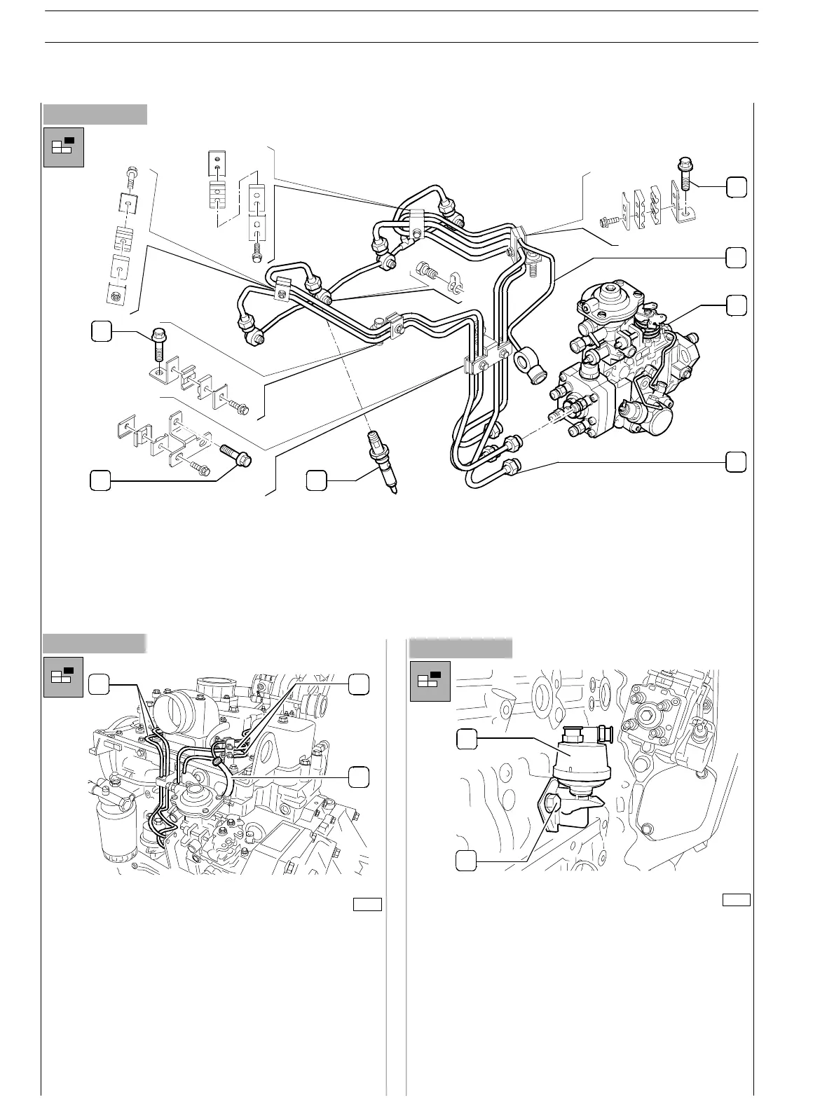
- Disconnect the pipelines (1) and (2) that provide feed
and fuel recovery between pump and injectors; screw
out the nuts fixing the pipes to the pumping elements;
loosen th e fuel recovery pipe collar on the in jec tion
pump; operate on th e nuts assembled to the injectors
and loosen the screws fixing the fuel recovery pipeline;
loosen the screws holding the fixing brackets of such
pipelines (1,6, and 7, Figure 11); pipe the pipeline ends.
- Disassemble the injector s and remove them from their
slot: remove the gaskets.
Figure 13
75678
- Loosen the t wo fixing screws and disassemble priming
pump.
7
6
5
1
2
3
4
1. Rear bracket fixing screw (on suction collector plate) − 2. Fuel recovery pipeline to pump − 3. Rotary feed pump − 4.
Connection nut to pumping elements − 5. Injecto r − 6. Bracket fixing screw to injection pump side− 7. Front bracket fixing
screw (on suction collector plate)
1
1
2
2
1
SECTION 3 − DUTY − INDUSTRIAL APPLICATION
12
E NG I NE S
ED. FEBUARY 2003
zs