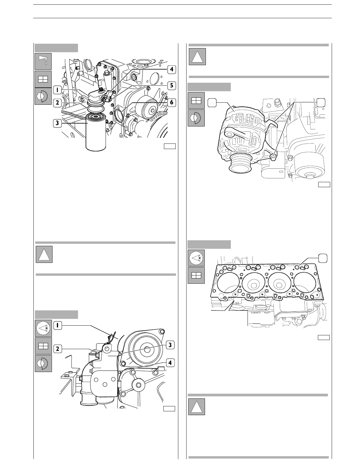
Figure 62
Figure 63
- Lubricate the fixing ring (2) using engine oil and place it
on the oil filter (3).
- Manually start the oil filter (3) on the bearing union (1)
until counter−boring, further screw up the oil filter (3)
by 3/4 turn.
- Apply, (if needed) new fixing ring on the oil
temperature/pressure sensor (4) and assemble it to the
bearing (1) tightening the fixing screws to t h e prescribed
couple.
- Assemble the alternator bearing (1) ensuring that the
pins (3 and 4) are against the engine block.
- Tighten the screws (2) and lock them to the prescribed
couple.
Figure 64
- Plac e the gasket (1) over the block.
The choice of the gasket’s thickness shall be made in
consideration of the cy lin der protrusion measured with
respect to the block’s upper surface.
- Place a new fixing ring on the block housing (6).
Figure 65
76113
!
In some applications, the bearing of the exchanger
shall be assembled to a screw threaded un ion
connected to the filter on the opposite side of the
engin e, throughout two pipelines (see picture 2).
76114
!
Before assembly, always check that the threads of the
ports and of the screws have no evidence of tear and
wear nor dirt.
12
75686
- Reassemble the alternator (1).
- Tighten the screw (2) and lock it t o the prescribed
couple.
75706
2830006
2830006
1
!
Verify that the engine block stand is clean.
Do no t grease the gasket. It is recommended to keep
the gasket inside packaging until assembly to the
cylinder head.
Gasket assembly shall be made following the
direction of wording printed on the gasket itself so
that this will be readable as indicated in the picture.
SECTION 3 − DUTY − INDUSTRIAL APPLICATION E NG I NE S
25
ED. FEBUARY 2003
zs