Figure 146
Figure 147
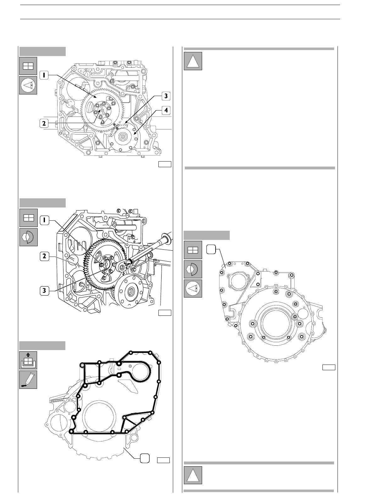
- Orient engine drive shaft (4) and camshaft (2) taking care
that in phase of assembly of the driving gear (2) to the
camshaft, the notches mar ked on the gear s (1 and 3)
shall match.
!
It is necessary an d essential to clean the surface to
be sealed in order to achieve excellent tight seal.
Apply sealing LOCTITE 5205 on the box in order to
form a kerbstone of a few mm. Diameter. It must be
uniform (no crumbs), with no air blisters, thinner or
irregu lar zones.
Any eventual imperfection shall be cor rect as soon
as possible.
Avoid using material in excess to seal the joint. Too
mu ch sealing material would drop out on both sides
of the joint and obstr uct lubricant passages.
After having completed seal application, the joints
must be immediately assembled (10−20 minutes
time).
- Tighten th e screws (1) fixing the gear to the camshaft (3)
and lock them to the prescr ibed couple .
Figure 148
Figure 149
- Reassemble the box (1) to th e engine block, tighten the
fixing screws in the same position as found out during
disassembly and fix the screws to the locking c ouples
listed here below, following the o rder as shown in the
picture.
Screws M12 75 ÷ 95 Nm
Screws M10 44 ÷ 53 Nm
70212
70213
75708
1
DIAGRAM SHOWING SEALING LOCTITE 5205
APPLICATION.
75709
1
2
3
4
5
6
7
8
9
10
11
12
13
14
15
16
17
18
19
20
21
1
DIAGRAM SHOWING SCREW
TIGHTENING TO FIX FLYWHEEL COVER BOX.
!
Before assembly, always check that the threads of the
ports and of the screws have no evidence of tear and
wear nor dirt.
SECTION 3 − DUTY − INDUSTRIAL APPLICATION
50
E NG I NE S
ED. FEBUARY 2003
zs