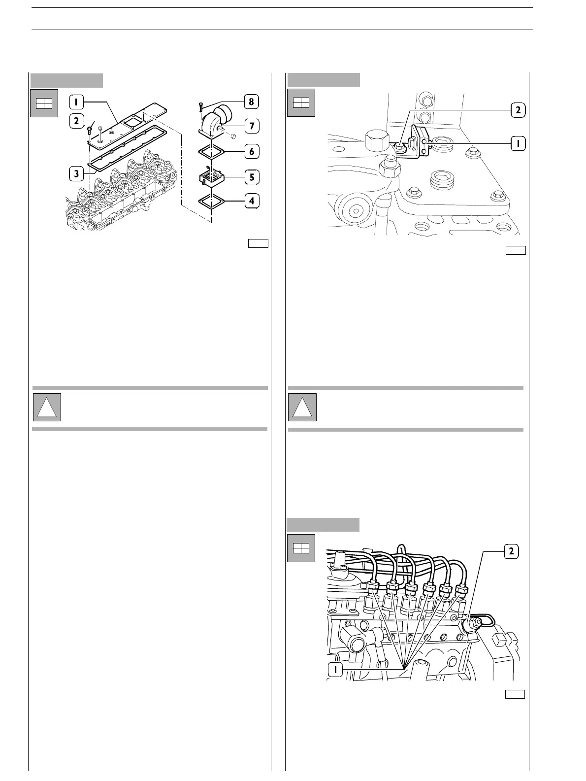
Figure 187
- Apply on the surface joining the suction manifold plate
(1) t he gasket (3) and provide. Fixing the screws (2) to
the prescribed couple.
- If the pipe (7) of the suction manifold plate (1) has been
removed, reassemble it after having fit a n ew gasket (6).
- Tighten the screws (8) to the prescribed couple.
Figure 188
!
For the version s provided with h eater, also assemble
components (4) and (5).
- Also assemble the brackets (1) fixing the fuel pipelines
to the injectors: use the same screws (2) fixing the
manifold plate as shown in th e picture.
- Also assemble feed pump (see specific procedure) and
the power take−off underneath.
!
Pump assembly requires specific procedure as
reported at the end of the hereby section.
76207
76208
Figure 189
- Assemble the pipes (1) and (2) providing fuel feed and
recov ery between pump and injectors;
Screw up the locking nuts and tighten the screws fixing
the fuel recovery manifold.
76138
SECTION 3 − DUTY − INDUSTRIAL APPLICATION
60
E NG I NE S
ED. FEBUARY 2003
zs