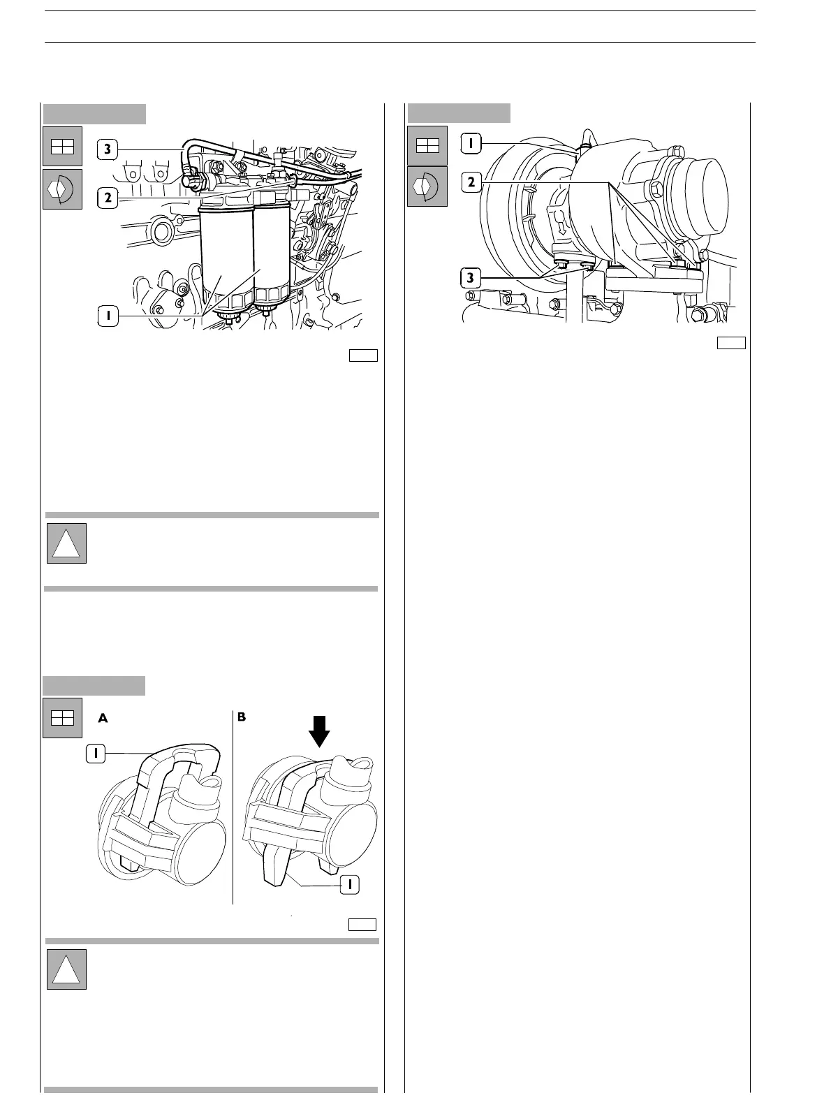
Figure 194
- Assemble the fuel filter bearin g (4) to the bracket fixed
to the engine head.
- Conn ec t the fuel pipelines (2 and 3) respectively from
priming pump to filter bearin g and from this last one to
feed pump.
-
Use acceptable tools to install fuel filter (I).
Figure 195
Proceed assembling the turbocharger :
- Hold the turbochar ger and place it on th e exhaust
manifold after having interposed the gasket.
- Screw up the fixing nuts (2) of the turbocharger to the
exhaust manifold tightening them to the prescribed
couple.
- Tighten the lubrication pipe fixing rin g. O per ate in t he
same way on the other end of the pipe. Connect it to
the upper part of the heat exchanger.
- Assemble the turbocharger lubr ication exhau st pipe by
tightening the screws (3); connect the end to the engine
block..
To complete engine assembly it is necessary to remove it
from the turning stand.
-
Use acceptable tools to hold the engine and loosen the
screws fixing the brackets to the turning stand.
- Disassemble the br ackets from the engine after having
properly put it on a wooden bearing.
Figure 196
!
The filter shall be priory filled with fuel t o facilitate
feed system b leed operations.
76141
70126
!
To connect fuel pipelines (2 and 3, Figure 194) in low
pressure from the relating connection unions it is
necessary to press the locking fastener (1) as shown
in picture B.
After having connected the pipeline, reset the
fastener (1) into block position as shown in picture
A.
76143
SECTION 3 − DUTY − INDUSTRIAL APPLICATION
62
E NG I NE S
ED. FEBUARY 2003
zs