3.4.- DEVICE TERMINALS
The CVM-A terminals are distributed between the upper and lower face of the device.
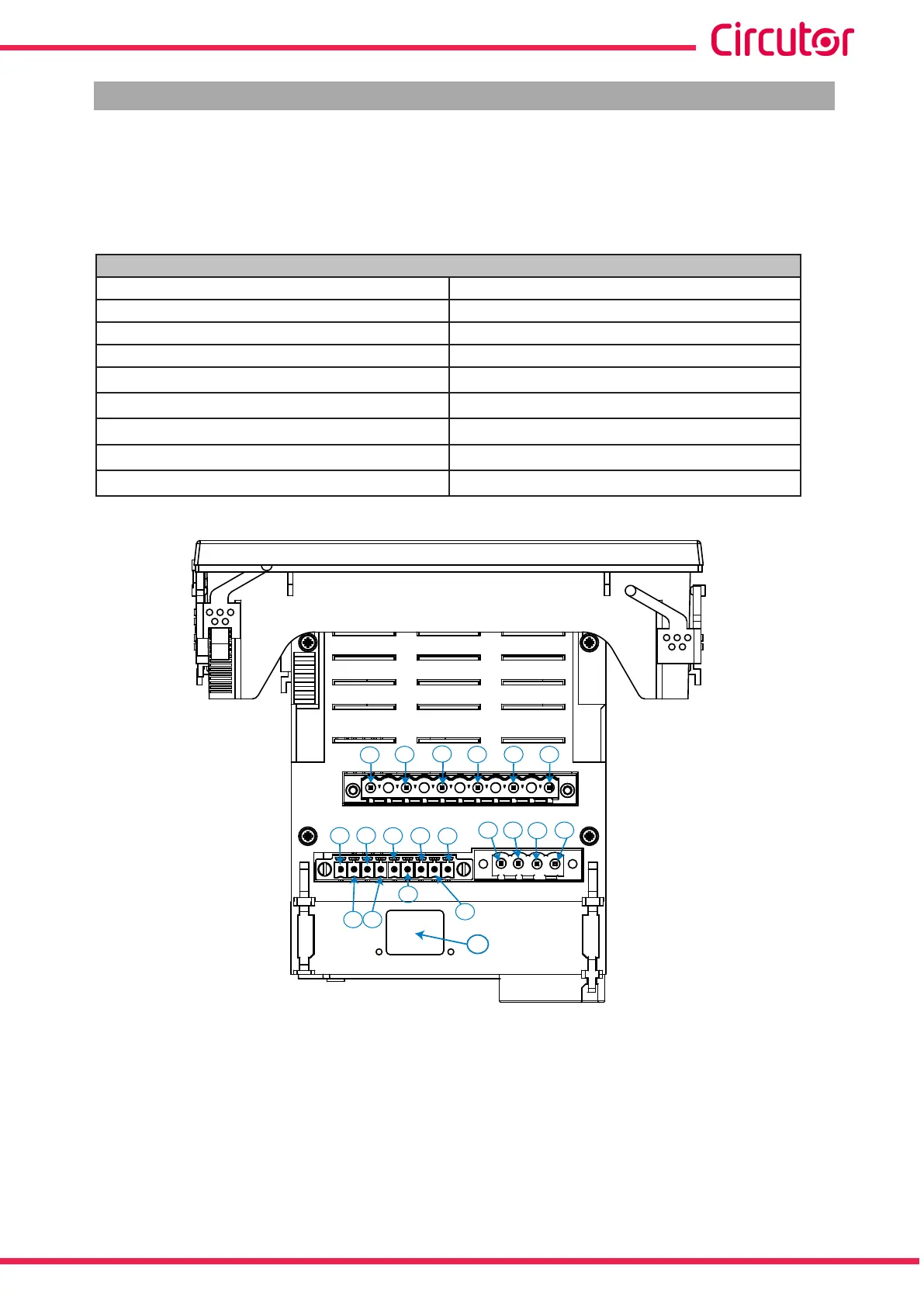
3�4�1�- TERMINALS ON THE UPPER FACE
Table 6:List of terminals on the upper face of the CVM-A�
Terminals of the top side of the device
1: V
REF
, Reference voltage input 10: T
1
, Digital output of transistor 1
2: N
REF
, Reference voltage neutral 11: T
2
, Digital output of transistor 2
3: N, Voltage input neutral 12: T
C
, Common digital output of transistor
4: V
L3
,Voltage input L3
13: A(+), RS485
5: V
L2,
Voltage input L2
14: B(-), RS485
6: V
L1,
Voltage input L1
15: S, GND for RS-485
7: I
1
, Digital input 1
16, 17: R
1
, Relay digital output 1
8: I
2
, Digital input 2
18, 19: R
2
, Relay digital output 2
9: I
c
, GND for digital inputs
20: Ethernet
1
2
3
4 5 6
7
10
9
12
11
13
14
15
8
16 17
18
19
20
Figure 1: CVM-A terminals, upper face�
13
Instruction Manual
CVM-A1000 - CVM-A1500