The device must be connected to a power circuit that is protected with gL fuses (IEC 269) or
M fuses, with a rating of 1 to 2 A. It must be tted with a circuit breaker or equivalent device for
disconnecting the device from the power supply mains.
The power and voltage measuring circuit must be connected with cables that have a minimum
cross-section of 1mm
2
and the wires must to endure a temperature at least 77 degrees.
The secondary line of the current transformer will have a minimum cross-section of 2.5 mm
2
.
Current needs to be measured via external current transformers providing reinforced insulation.
3.3.- CVM-A1x00-FLEX: ROGOWSKI SENSORS
The CVM-A1x00-FLEX model measures currents using exible sensors, based on the Ro-
gowski coil principle.
The exibility of the sensor allows it to measure an alternating current irrespective of the posi-
tion of the conductor.
CIRCUTOR has a Rogowski sensor model that can be used with the CVM-A1x00-FLEX�
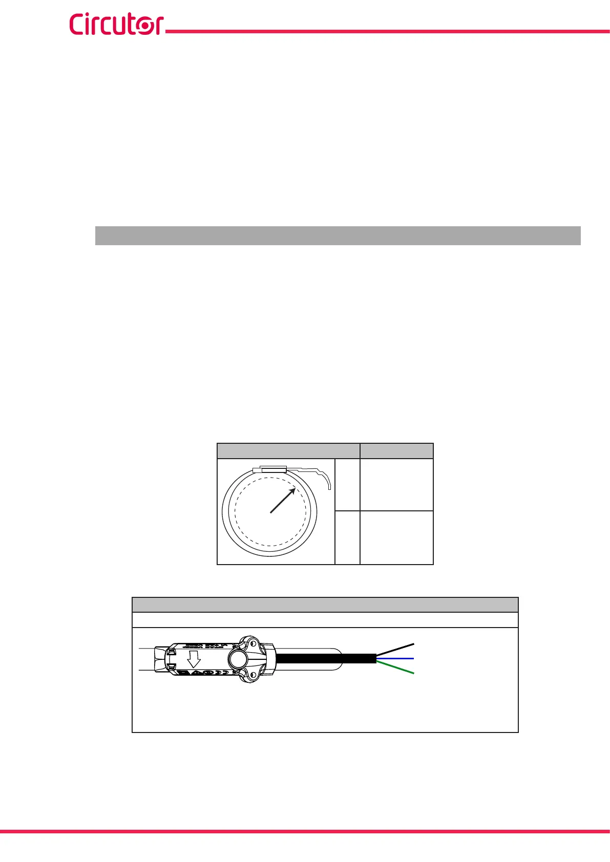
Table 5 shows the connection of the sensors and Table 4 the maximum position error.
Note: For more information, consult the corresponding sensor guide.
Table 4:Position error�
Position Error
A
B
A ± 1%
B A ± 3%
Table 5:Probe cable terminal connections
Probe cable terminal connections
FLEX-MAG
Canal de medida / Measuring channel
Común / Common
Shield
Black : Shield (SHLD)
Blue: Common (C)
Green: Measuring channel (L1, L2, L3, N)
12
CVM-A1000 - CVM-A1500
Instruction Manual