Table 16:List of Datalogger LEDs�
LED Status Function
ACT
Power on No activity in the bus
Blinking light Activity in the bus
LINK
Power on Module connected
Off Module disconnected
LINKACT
Figure 37: Datalogger LEDs�
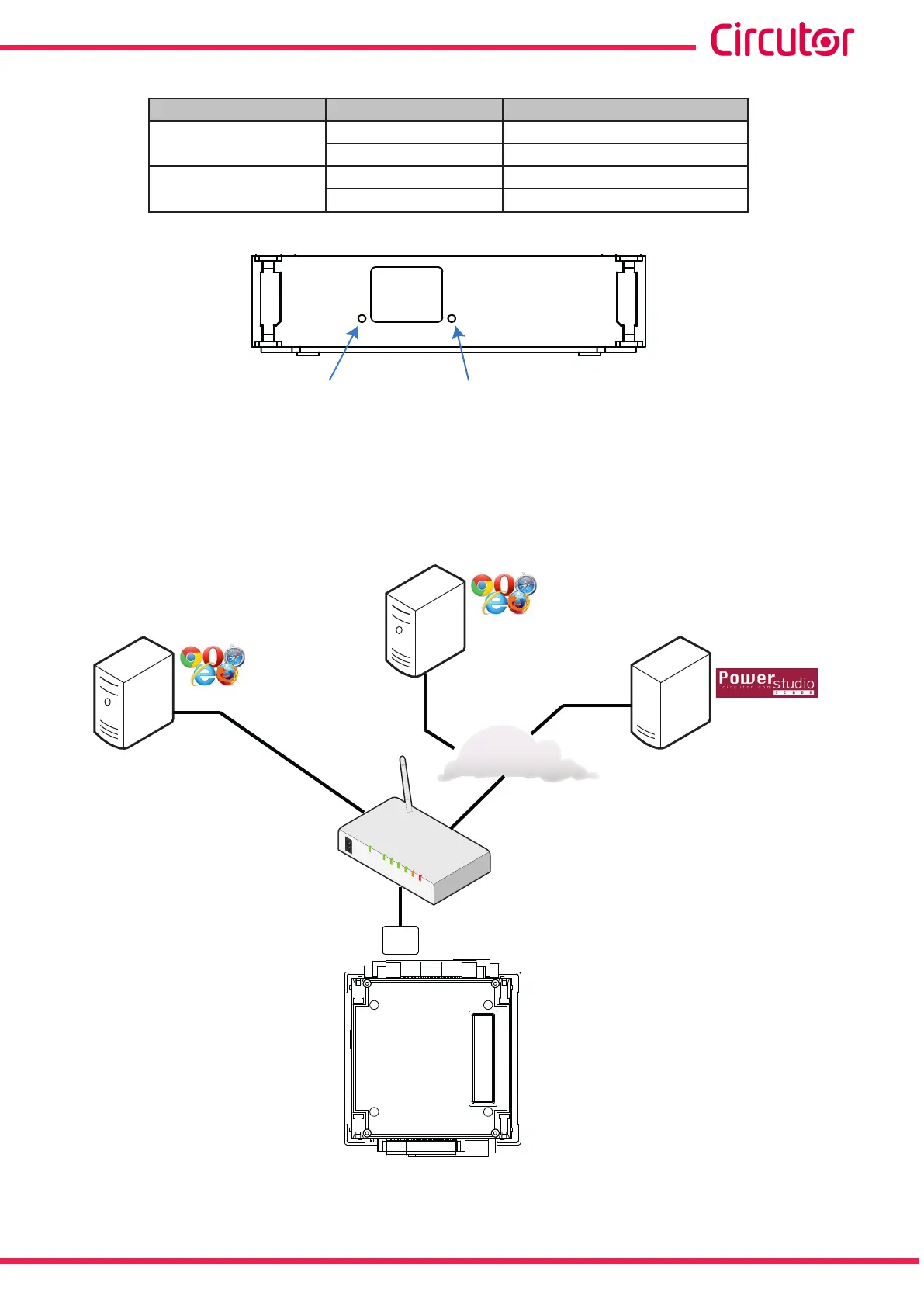
4�8�3�- CONNECTION DIAGRAM
PC
Ethernet
ROUTER
INTERNET
PC
CVM-A
With a browser
compatible with HTML5
With a browser
compatible with HTML5
SERVER
Optional
Figure 38:Connection diagram, Datalogger�
55
Instruction Manual
CVM-A1000 - CVM-A1500