4.5.- LED INDICATORS
The CVM-A device features:
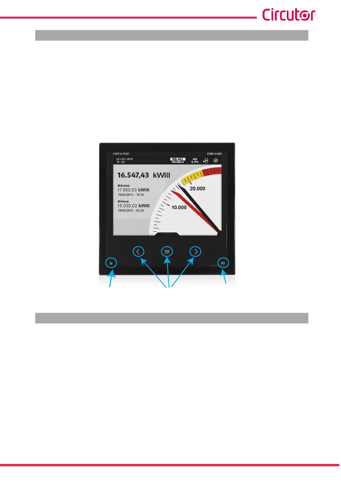
- A CPU LED, which indicates that the device is working correctly with a 1 second ash-
ing. A ashing of 0.5 seconds indicates that an error has occurred.
- An ALARM LED, which indicates that an alarm has been activated with the LED ash-
ing. If there is no alarm it remains switched off.
-3 LED on the navigation keys, which stay switched on with low current; when any of
the 3 keys are pressed they all come on at maximum current.
Keys
CPU
Alarm
Figure 36:LED indicators of the CVM-A�
4.6.- INPUTS
The CVM-A has two programmable digital inputs (terminals 7 and 8 in Figure 1) for working as:
Logic input.
Impulse input.
Tariff selection.
See “5.7.18.- DIGITAL INPUTS.” to congure the inputs.
In “5.1.9.- INTEGRATED FUNCTIONS.” and in “5.6.2 INTEGRATED FUNCTIONS.” you can see
the status and conguration of the programmed digital inputs.
The selected tariff can be determined in accordance with the status of the inputs, as shown in
Table 15.
53
Instruction Manual
CVM-A1000 - CVM-A1500