A bar chart with the indications of the instantaneous value, maximum and minimum
values and alarms, see “4.4.3. CENTRAL AREA”�
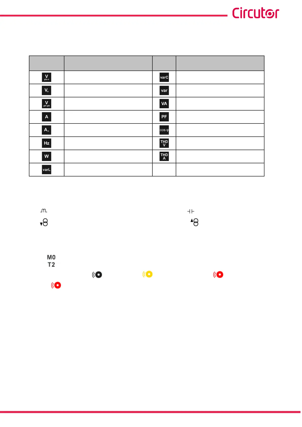
Table 17: Instantaneous parameters�
Icon
Display 1 parameter
Instantaneous parameters
Icon
Display 1 parameter
Instantaneous parameters
Phase-Neutral Voltage Capacitive reactive power
(6)
Neutral voltage Total reactive power
(6)
Phase-Phase Voltage Apparent power
(6)
Current Power factor
(6)
Neutral Current
(5)
Cosine phi III
(6)
Frequency Voltage THD
(6)
Active power
(6)
Current THD
(6)
Inductive reactive power
(6)
(5)
In the CVM-A1x00-FLEX version, the neutral current is a calculated parameter, except in Single-Phase connec-
tion mode, where it is not supported.
(6)
The following icons appear for all these parameters on the screen:
Indicating that the parameter refers to inductive or capacitive energy.
Indicating that the parameter refers to consumed or generated energy.
If the 2 icons light up at the same time, it means the installation is not properly connected.
If there is an alarm associated with the variable being displayed, the following will be shown:
The module with which the alarm is associated.
The associated output in the module.
The alarm status: not activated, pre-alarm activated, alarm activated.
The icon flashes during the delay time in the alarm connection (ON) and
disconnection (OFF).
61
Instruction Manual
CVM-A1000 - CVM-A1500