11-4
Catalyst 2950 and Catalyst 2955 Switch Software Configuration Guide
78-11380-10
Chapter 11 Configuring Interface Characteristics
Using the Interface Command
Connecting Interfaces
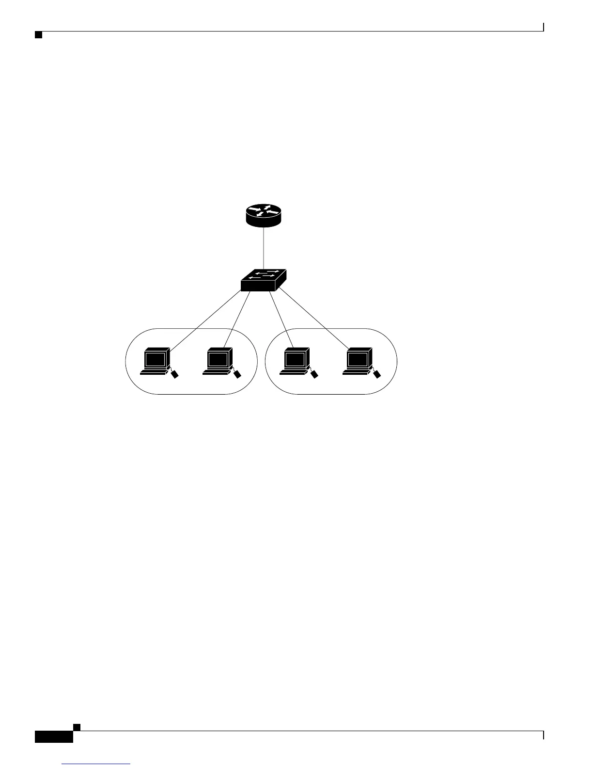
Devices within a single VLAN can communicate directly through any switch. Ports in different VLANs
cannot exchange data without going through a routing device or routed interface.
With a standard Layer 2 switch, ports in different VLANs have to exchange information through a router.
In the configuration shown in Figure 11-1, when Host A in VLAN 20 sends data to Host B in VLAN 30,
it must go from Host A to the switch, to the router, back to the switch, and then to Host B.
Figure 11-1 Connecting VLANs with Layer 2 Switches
Using the Interface Command
To configure a physical interface (port), use the interface global configuration command to enter interface
configuration mode and to specify the interface type, slot, and number.
• Type—Fast Ethernet (fastethernet or fa) for 10/100 Ethernet, Gigabit Ethernet (gigabitethernet or
gi), or LRE (longreachethernet or lo)
• Slot—The slot number on the switch (always 0 on this switch).
• Port number—The interface number on the switch. The port numbers always begin at 1, starting at
the left when facing the front of the switch, for example, fastethernet 0/1, fastethernet 0/2. If there
is more than one interface type (for example, 10/100 ports and Gigabit Ethernet ports), the port
number starts again with the second interface type: gigabitethernet 0/1, gigabitethernet 0/2.
You can identify physical interfaces by physically checking the interface location on the switch. You can
also use the Cisco IOS show privileged EXEC commands to display information about a specific
interface or all the interfaces on the switch. The remainder of this chapter primarily provides physical
interface configuration procedures.
This section describes how to configure all types of interfaces and how to configure a range of interfaces:
• Procedures for Configuring Interfaces, page 11-5
• Configuring a Range of Interfaces, page 11-5
• Configuring and Using Interface-Range Macros, page 11-7
Host A
Switch
Cisco router
VLAN 20
Host B
VLAN 30
46647