13-16
Catalyst 2950 and Catalyst 2955 Switch Software Configuration Guide
78-11380-10
Chapter13 Configuring LRE
Configuring LRE Ports
To unlock a port, use the no rate selection profile lock interface configuration command.
Link Qualification and SNR Margins
When rate selection is running, the SNR is used as an indicator of link quality. The switch does not
provide any internal mechanism to ensure link quality. There can be different requirements for link
quality, depending on the required bit-error rate and the noise level of the environment. A noisier
environment would require a higher SNR to be able to provide a stable link. A lower bit-error rate would
require a higher SNR. Typically a 6-dB margin provides an error rate of 10
-21
bits.
To provide link stability, you should add a margin to the required SNR. You can configure your margins
to an amount that is appropriate for the noise level of your environment. Increasing the margin
requirement can cause the system to choose a lower profile, which would in turn translate to a lower rate
but with a higher reach.
The switch does not guarantee any margins after a link is activated; margins are only guaranteed only
when the link is established. When a link is activated, if the SNR requirements do not match the
configured margin level, the link is not established.
Downstream means the remote end of the link, and upstream the local end. The link has to satisfy both
the local and remote margin requirements. If either one is not met, the link is advertised as down. This
command has no significance if rate selection is disabled on the interface.
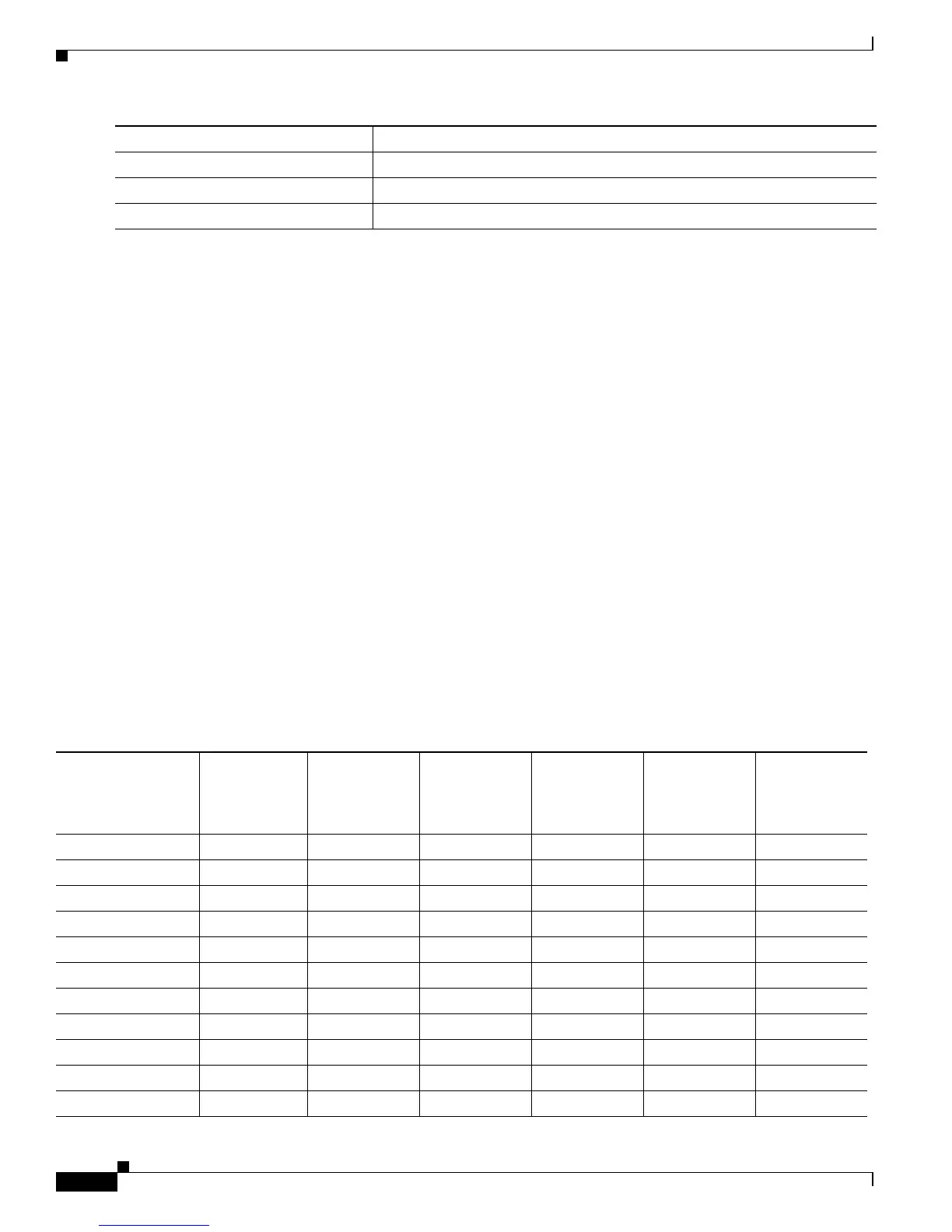
Table 13-6 and Table 13-8 list the SNR requirements for downstream rates for different profiles.
Table 13-7 and Table 13-9 list the SNR requirements for upstream rates for different profiles.
Step 4
end Return to privileged EXEC mode.
Step 5
show controllers lre profile details Verify the change.
Step 6
copy running-config startup-config (Optional) Save your entries in the configuration file.
Command Purpose
Table 13-6 SNR Requirements for Downstream Rates for the Catalyst 2950ST-8 LRE and the Catalyst 2950ST-24 LRE
Switches
Profile
Gross Data
Rate
Quadrature
Amplitude
Modulation
(QAM)
Theoretical
Minimum SNR Low Noise SNR
Medium Noise
SNR
High Noise
SNR
LRE-4-14.171619212326
LRE-7 8.333 16 19 21 23 26
LRE-8 9.375 64 25 27 29 32
LRE-5 6.25 8 16 19 21 24
LRE-10 12.5 64 25 27 29 32
LRE-15 16.667 256 31 33 35 39
LRE-10-5 12.5 64 25 27 29 32
LRE-10-3 12.5 64 25 27 29 32
LRE-10-1 12.5 64 25 27 29 32
LRE-15-5 16.667 256 31 33 35 39
LRE-15-3 16.667 256 31 33 35 39