13-20
Catalyst 2950 and Catalyst 2955 Switch Software Configuration Guide
78-11380-10
Chapter13 Configuring LRE
Configuring LRE Ports
Configuring LRE Link Monitor
When link monitor is enabled, an LRE switch feature tracks undesirable or interesting conditions on a
link or takes system-defined actions after certain thresholds are reached.
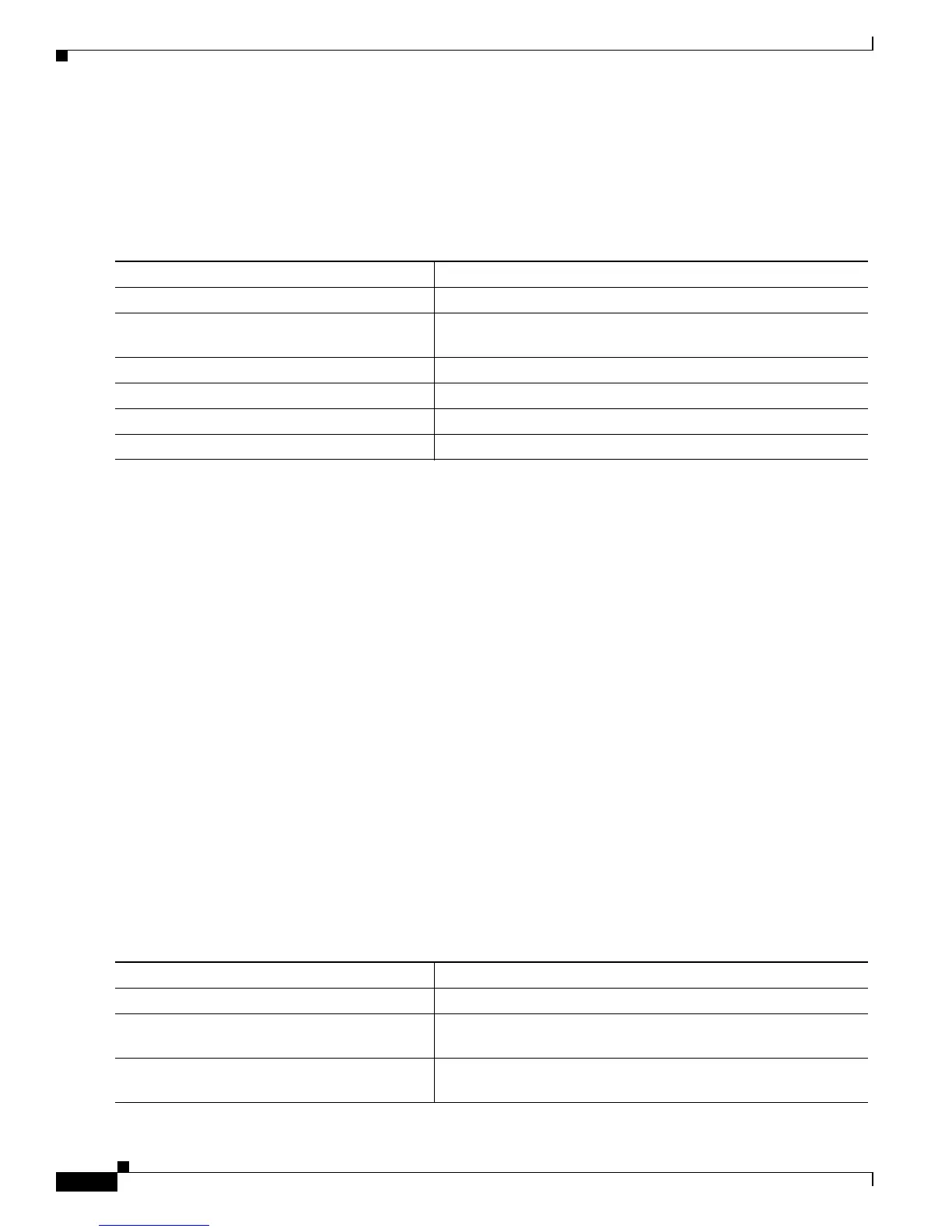
Beginning in privileged EXEC mode, follow these steps to enable link monitor:
To disable the link monitor feature, use the no link monitor interface configuration command.
Configuring LRE Interleave
The interleave feature provides maximum protection against small interruptions on the LRE link but
delays data transmission. You can configure the interleave delay on LRE interfaces.
A lower value of the interleave block size means less tolerance to noise and causes a lower latency of
frame transmission. For example, lower values of the interleave block size can be used for voice
applications. A higher value of the interleave block size means higher tolerance to noise and causes
higher latency in the frame transmission. For example, higher values of the interleave block size can be
used for data applications.
If a lower latency of frame transmission is required, you can use a lower interleave value, but the LRE
switch will have less tolerance to noise.
Follow these guidelines for configuring the interleave delay:
• Interleave delay is applicable only when the non-LL profiles are used. Existing LL profiles are
supported.
• Interleave block size values of 0, 1, 2, 8, or 16 are supported.
• Different ports with the same profile can have different interleave settings.
Beginning in privileged EXEC mode, follow these steps to set the interleave block size on a specific LRE
port:
Command Purpose
Step 1
configure terminal Enter global configuration mode.
Step 2
interface interface-id Specify the LRE port to be configured, and enter interface
configuration mode.
Step 3
link monitor Enable LRE link monitoring on an LRE port.
Step 4
end Return to privileged EXEC mode.
Step 5
show running-config Verify the change.
Step 6
copy running-config startup-config (Optional) Save your entries in the configuration file.
Command Purpose
Step 1
configure terminal Enter global configuration mode.
Step 2
interface interface-id Specify the LRE port to be configured, and enter interface
configuration mode.
Step 3
interleave downstream value upstream value Enter the downstream and upstream values. Supported values for
interleave block sizes are 0, 1, 2, 8, or 16.