17-24
Catalyst 2950 and Catalyst 2955 Switch Software Configuration Guide
78-11380-10
Chapter 17 Configuring VLANs
Configuring VLAN Trunks
Load Sharing Using STP Path Cost
You can configure parallel trunks to share VLAN traffic by setting different path costs on a trunk and
associating the path costs with different sets of VLANs. The VLANs keep the traffic separate. Because
no loops exist, STP does not disable the ports, and redundancy is maintained in the event of a lost link.
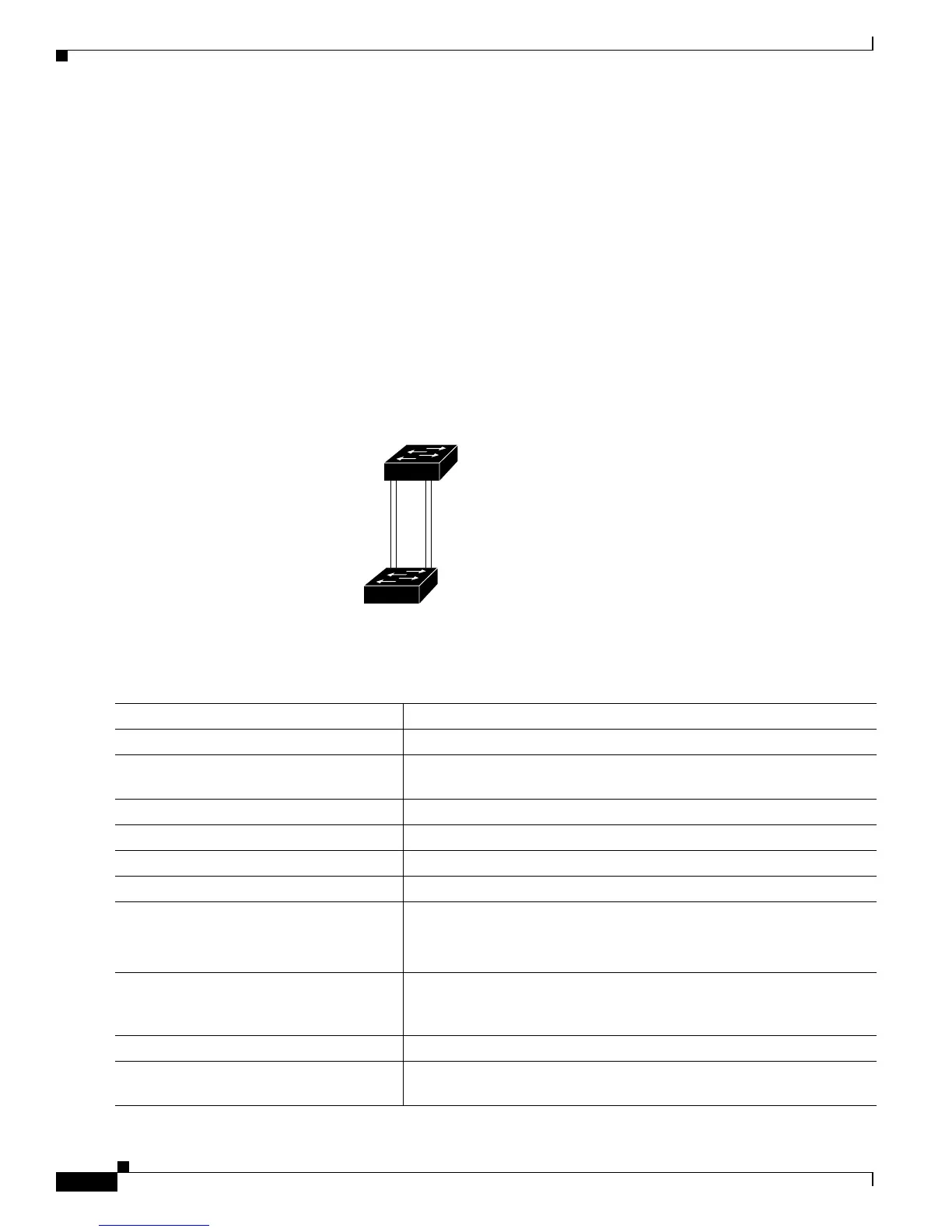
In Figure 17-4, Trunk ports 1 and 2 are 100BASE-T ports. The path costs for the VLANs are assigned
as follows:
• VLANs 2 through 4 are assigned a path cost of 30 on Trunk port 1.
• VLANs 8 through 10 retain the default 100BASE-T path cost on Trunk port 1 of 19.
• VLANs 8 through 10 are assigned a path cost of 30 on Trunk port 2.
• VLANs 2 through 4 retain the default 100BASE-T path cost on Trunk port 2 of 19.
Figure 17-4 Load-Sharing Trunks with Traffic Distributed by Path Cost
Beginning in privileged EXEC mode, follow these steps to configure the network shown in Figure 17-4:
90573
Switch A
Switch B
Trunk port 1
VLANs 2 – 4 (path cost 30)
VLANs 8 – 10 (path cost 19)
Trunk port 2
VLANs 8 – 10 (path cost 30)
VLANs 2 – 4 (path cost 19)
Command Purpose
Step 1
configure terminal Enter global configuration mode on Switch A.
Step 2
interface fastethernet 0/1 Enter interface configuration mode, and define Fast Ethernet port 0/1 as
the interface to be configured as a trunk.
Step 3
switchport mode trunk Configure the port as a trunk port.
Step 4
exit Return to global configuration mode.
Step 5
Repeat Steps 2 through 4 on Switch A interface Fast Ethernet 0/2.
Step 6
end Return to privileged EXEC mode.
Step 7
show running-config Verify your entries.
In the display, make sure that interfaces Fast Ethernet 0/1 and Fast
Ethernet 0/2 are configured as trunk ports.
Step 8
show vlan When the trunk links come up, Switch A receives the VTP information
from the other switches. Verify that Switch A has learned the VLAN
configuration.
Step 9
configure terminal Enter global configuration mode.
Step 10
interface fastethernet 0/1 Enter interface configuration mode, and define Fast Ethernet port 0/1 as
the interface to set the STP cost.