5-55
Hardware Installation Guide for Cisco 4000 Series Integrated Services Routers
OL-32185-02
Chapter 5 Install and Upgrade Internal Modules and FRUs
Remove and Replace Cisco 4000 Series ISRs Power Supplies
• Ensure that the chassis ground is connected on the chassis before you begin installing the DC power
supply. Follow the steps provided in the “Chassis Grounding” section on page 3-19.
Wire the DC Input Power Source on Cisco 4331 ISR
The Cisco 4331 ISR DC power supply supports 12V/21A output with the DC input range from 24 to 60
VDC.
Note The input current should be less than 6.3 A at 48 VDC. It is recommended to use slow blow fuse and
have the input fuse value less than or equal to 25 A.
The Cisco 4331 ISR DC power supply has a terminal block that is installed into the power supply
terminal block header.
To wire the DC input power source:
Step 1 Ensure that the power switch is in the standby position.
Step 2 Insert the power supply in the power-supply slot, and gently push it into the slot.
Step 3 Wire can be stripped and terminated directly to the power supply terminal block, or a crimp style spade
terminal lug can be used. If you are using a terminal lug, follow the manufacturer's instructions for
terminating the lug to the wire. If terminating directly to the terminal block using bare wire, follow the
instructions in the Figure 5-37. Use a wire-stripping tool to strip each of the two wires coming from the
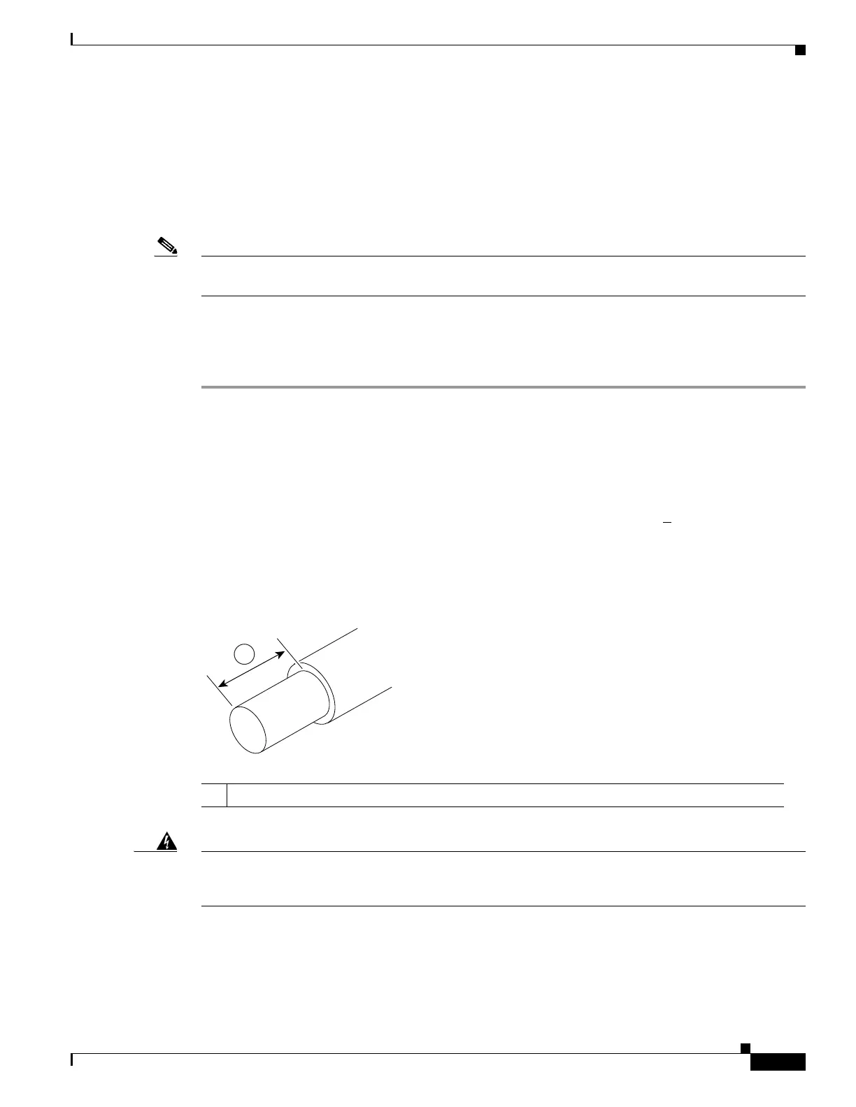
DC input power source and strip the wires to approximately 0.39 inch (10 mm) +
0.02 inch (0.5 mm). It
is recommended that 14 AWG insulated wire be used. Do not strip more than the recommended length
of wire because doing so could leave the wire exposed from the terminal block. Figure 5-38 shows a
stripped DC input power source wire.
Figure 5-43 Stripped DC Input Power Source Wire
Warning
An exposed wire lead from a DC input power source can conduct harmful levels of electricity. Be sure
that no exposed portion of the DC input power source wire extends from the terminal block.
Statement
122
Step 4 Identify the positive and negative feed positions for the terminal block connection. The wiring sequence
is:
1. Positive (+) lead wire (right)
2. Negative (–) lead wire (left)
1 0.39 inch (10 mm) is the recommended wire-strip length for the terminal block.

 Loading...


