5-56
Hardware Installation Guide for Cisco 4000 Series Integrated Services Routers
OL-32185-02
Chapter 5 Install and Upgrade Internal Modules and FRUs
Remove and Replace Cisco 4000 Series ISRs Power Supplies
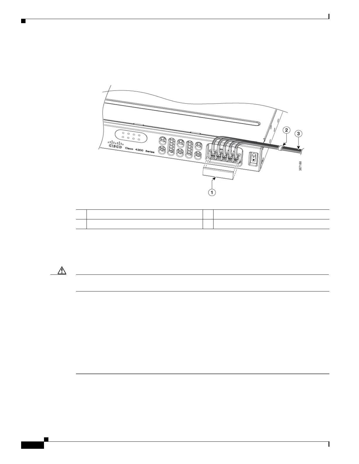
Step 5 Remove the plastic cover from the terminal block. Save the covers for reinstallation after you finish
wiring. See Figure 5-37.
Figure 5-44 Remove the Plastic Cover
Step 6
Insert the wires through the holes. Replace the plastic cover.
Step 7 Insert the exposed wire into the terminal block. Ensure that the wire lead is not placed outside the plastic
cover. Only wires with insulation should extend from the terminal block.
Caution Do not overtorque the terminal block captive screws. Ensure that the connection is snug, but the wire is
not crushed. Verify by tugging lightly on each wire to ensure that they do not move.
Step 8 Use a screwdriver to tighten the terminal block captive screws, as shown in Figure 5-40.
Step 9 Repeat these steps for the remaining DC input power source wire as applicable.
Step 10 Use a tie wrap to secure the wires to the rack, so that the wires are not pulled from the terminal block by
casual contact.
Step 11 Turn on the circuit breaker at the power source.
Step 12 If you have changed the standby switch to the standby position in step 1, turn the standby switch to the
On position.
The power supply LEDs illuminate green.
1 Plastic Cover 2 Cable Tie
3 DC Power Source

 Loading...


