1-6
Cisco ASA Series CLI Configuration Guide
Chapter 1 Information About Failover
Failover and Stateful Failover Links
Depending upon their network topologies, several primary/secondary failure scenarios exist in ASA
failover pairs, as shown in the following scenarios.
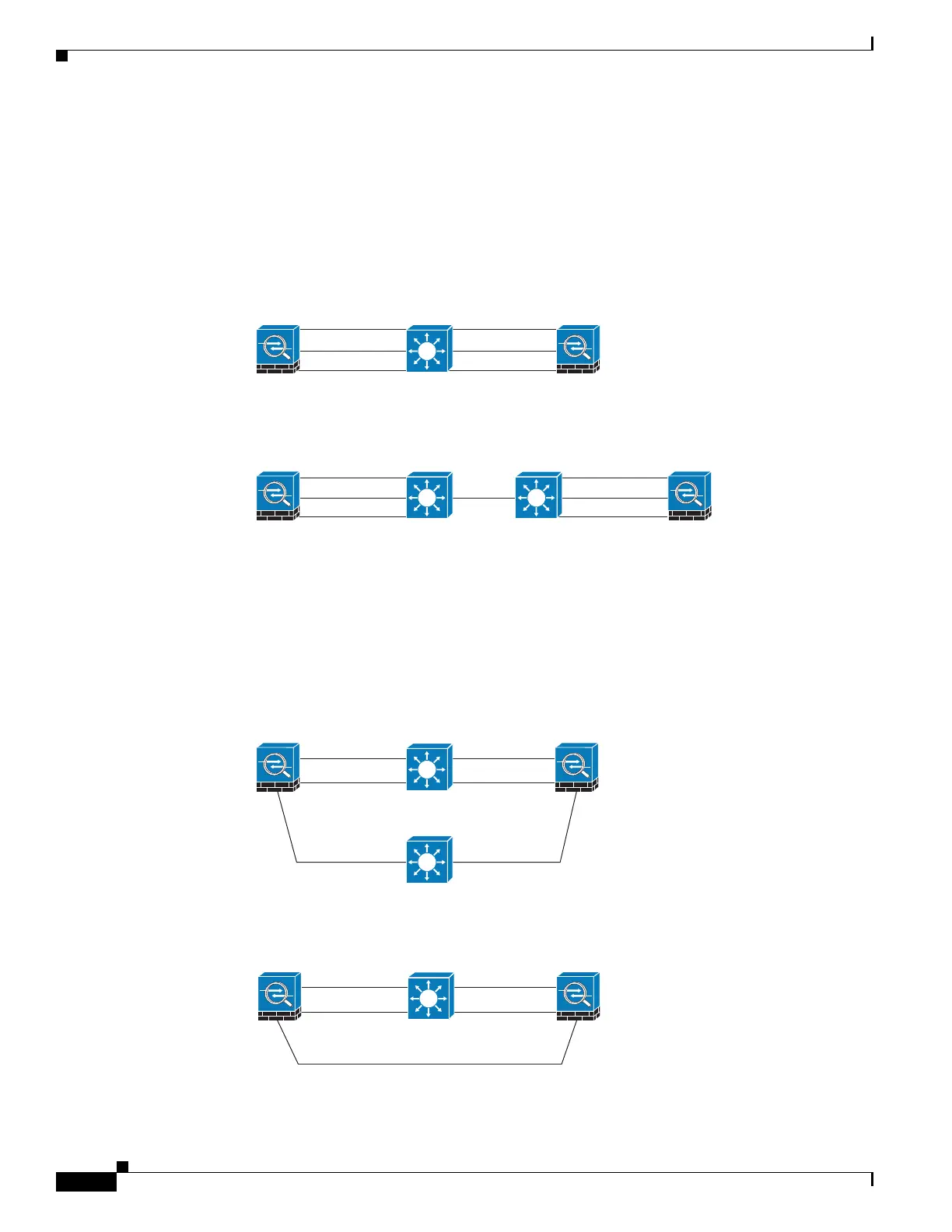
Scenario 1—Not Recommended
If a single switch or a set of switches are used to connect both failover and data interfaces between two
ASAs, then when a switch or inter-switch-link is down, both ASAs become active. Therefore, the
following two connection methods shown in Figure 1-1 and Figure 1-2 are NOT recommended.
Figure 1-1 Connecting with a Single Switch—Not Recommended
Figure 1-2 Connecting with a Double Switch—Not Recommended
Scenario 2—Recommended
To make the ASA failover pair resistant to failover interface failure, we recommend that failover
interfaces NOT use the same switch as the data interfaces, as shown in the preceding connections.
Instead, use a different switch or use a direct cable to connect two ASA failover interfaces, as shown in
Figure 1-3 and Figure 1-4.
Figure 1-3 Connecting with a Different Switch
Figure 1-4 Connecting with a Cable
36369
rimary
Failover link Failover link
Secondary
inside inside
36370
rimary
Failover link Failover link
Secondary
outside outside
inside
inside
ISL
rimary
236371
Failover link Failover link
Secondary
outsideoutside
Switch 2
inside inside
236372
Ethernet cable
Primary
Failover link Failover link
Secondary
outsideoutside
Switch 1
inside inside

 Loading...