1-7
Cisco ASA Series CLI Configuration Guide
Chapter 1 Information About Failover
Failover and Stateful Failover Links
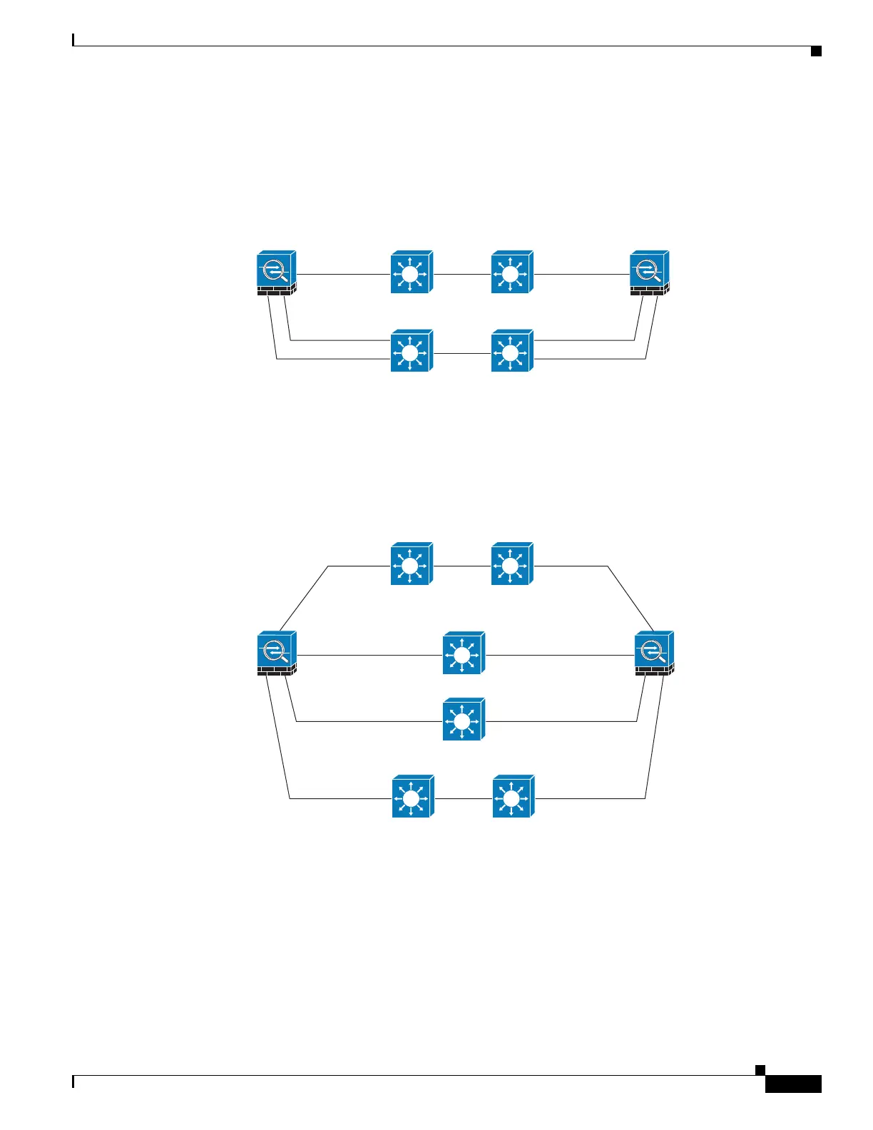
Scenario 3—Recommended
If the ASA data interfaces are connected to more than one set of switches, then a failover interface can
be connected to one of the switches, preferably the switch on the secure side of network, as shown in
Figure 1-5.
Figure 1-5 Connecting with a Secure Switch
Scenario 4—Recommended
The most reliable failover configurations use a redundant interface on the failover interface, as shown in
Figure 1-6 and Figure 1-7.
Figure 1-6 Connecting with Redundant Interfaces
236373
Failover link Failover link
Primary Secondary
outside outside
inside inside
ISL
ISL
Switch 3 Switch 4
Switch 1 Switch 2
236375
Primary
Active redundant
failover link
Active redundant
failover link
Standby redundant
failover link
Standby redundant
failover link
Secondary
outside outside
ISL
Switch 1 Switch 2
inside inside
ISL
Switch 5
Switch 3
Switch 6
Switch 4

 Loading...