Step 3 Repeat Step 2 for the other power modules installed in the chassis.
To prevent injury and damage to the equipment, always attach the ground and source DC power
cable to power module terminals in the following order: (1) ground to ground, (2) positive (+) to
positive (+), (3) negative (–) to negative (–).
Caution
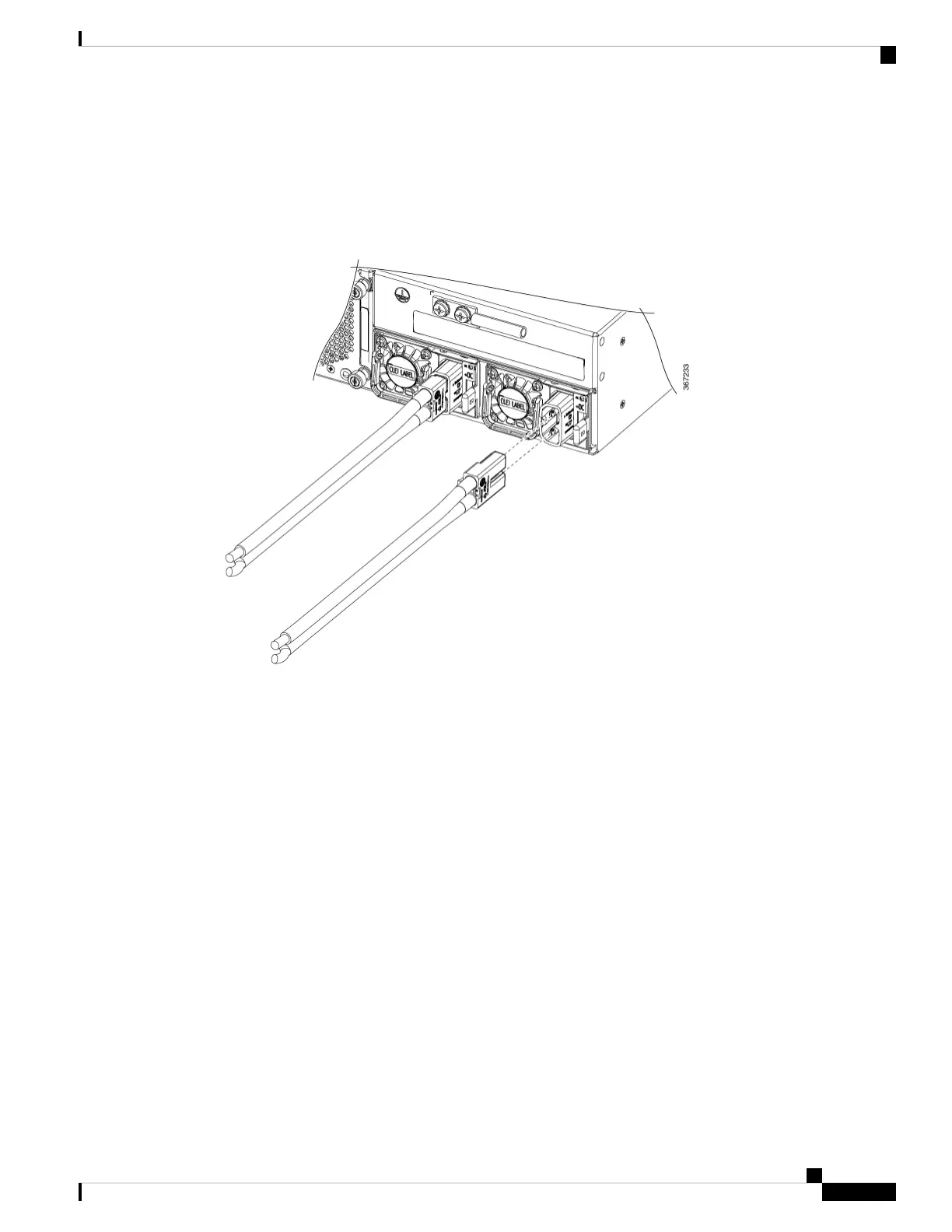
Figure 95: Cisco ASR 9901: Typical Power Connections for a Single DC Power Module
Cisco ASR 9901, ASR 9001, and ASR 9001-S Routers Hardware Installation Guide
97
Installing Modules and Cables in the Chassis
Connecting Power to a DC-Powered Router

 Loading...


