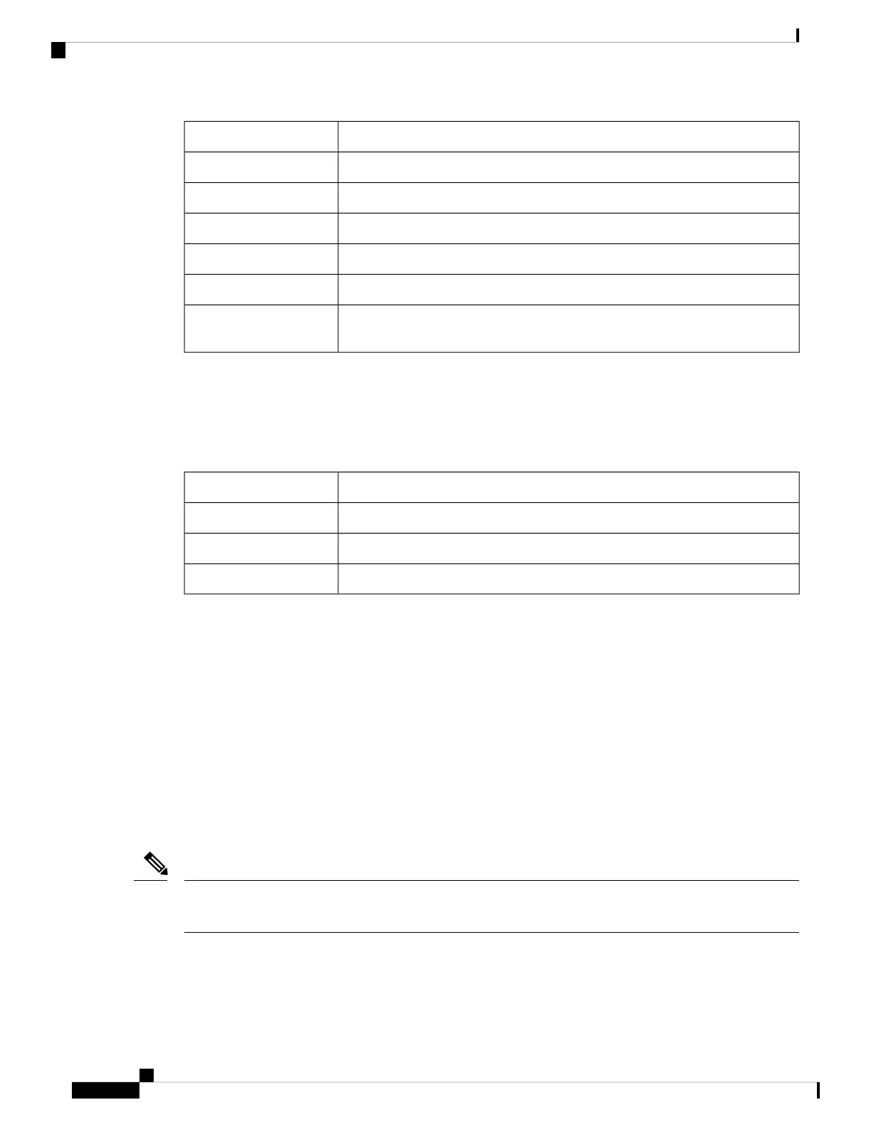
DescriptionLED Matrix Display
Cisco IOS XR Software is starting execution.IOXR
The RSP/RP is loading (MBI started and card preparing for activity).LDG
The software or configuration is incompatible with the RSP/RP.INCP
The RSP is in Out of Service, Maintenance mode.OOSM
The RSP is active (IOS-XR completely up and ready for traffic)ACT
The RSP failed anti-counterfeiting authentication and rebooted. If authentication
continues to fail, the RSP will be in a continuous reboot loop.
AUTH
LED Matrix CAN Bus Controller Error Display
The following table shows the error messages the LED matrix displays if the RSP card fails one of the power
on self tests.
Table 19: RSP LED Matrix CAN Bus Controller Status Display
DescriptionLED Matrix Display
Failed DDR RAM memory testPST1
Failed FPGA image cyclic redundancy checking (CRC) checkPST2
Failed card type and slot ID verificationPST3
Ethernet Ports and Status LEDs
The RP has two 8-pin media-dependent interface (MDI) RJ-45 Management LAN ports for 10 Mbps, 100
Mbps, and 1000Mbps Ethernet connections. These ports are labeled MGT LAN 0 and MGT LAN 1.
The transmission speed of the Ethernet port is not user-configurable. You set the speed through an auto-sensing
scheme on the RP, the speed is determined by the network to which the Ethernet port is connected. However,
even at an auto-sensed data transmission rate of 100 Mbps, the Ethernet port can only provide a usable
bandwidth of substantially less than 100 Mbps. You can expect a maximum usable bandwidth of approximately
12 Mbps when using an Ethernet connection.
These LEDs on the front panel indicate traffic status and port selection (see the following figure):
• LINK—Indicates link activity.
• ACT—Indicates which Ethernet port is selected (ETH 0 or ETH 1).
Because both ports are supported on the RP card, MGT LAN 0 is always on. MGT LAN 0 lights when it is
selected.
Note
Cisco ASR 9901, ASR 9001, and ASR 9001-S Routers Hardware Installation Guide
120
Troubleshooting the Installation
LED Matrix CAN Bus Controller Error Display

 Loading...


