• Chassis backplane power distribution—System transfers +12 VDC power from the power modules to
the chassis backplane and distributes it to all the cards through the backplane connectors. The fan tray
receives power from the chassis backplane and communicate to the RP CAN Bus controller.
• Processor subsystem—Includes the active Route Processor (RP) card with line card. The RP is equipped
with onboard processors. The RP downloads a copy of the Cisco software image to the line card processor.
• Cooling subsystem—The Cisco ASR 9001 Router has one fan tray (with 14 fans). The Cisco ASR 9901
Router has three fan trays. The fan trays circulate cooling air through the chassis.
Normal Router Startup Sequence
You can generally determine when and where the router failed during the startup sequence by checking the
status LEDs on the power modules and RP.
In a normal router startup sequence, this sequence of events and conditions occur:
Procedure
Step 1 The fan in each power module receives power and begins drawing air through the power supply.
The power module input power and output power indicators are on.
Step 2 The fans in the fan tray receive power and begin drawing air through the chassis.
The fan tray OK indicator is on.
Step 3 As the power-on and boot process progresses for the RP, the status of the RP appears on the front panel of
the card.
Identifying Startup Issues
The following table shows the LED states on the power modules (AC or DC), RP, and the fan tray after a
successful system startup.
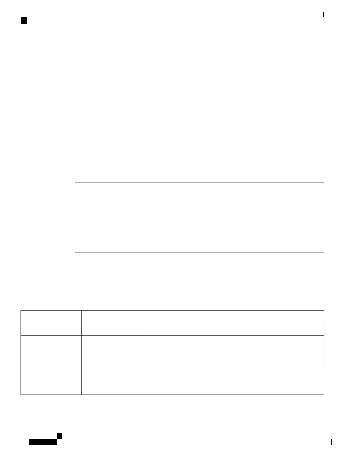
Table 15: LEDs at System Startup
Display Contents/LED Status and MeaningType of IndicatorComponent
Green: The line card is enabled and ready for use.Status LEDLine Card
Green (ON): Input AC power OK.
Amber (OFF): No fault is present. The correct power module voltages are
present and no faults have been detected.
Power status LEDsAC Power Modules
Green (ON): Input DC power OK.
Amber (OFF): No fault is present. The correct power module voltages are
present and no faults have been detected.
Power status LEDsDC Power Modules
Cisco ASR 9901, ASR 9001, and ASR 9001-S Routers Hardware Installation Guide
102
Troubleshooting the Installation
Normal Router Startup Sequence

 Loading...


