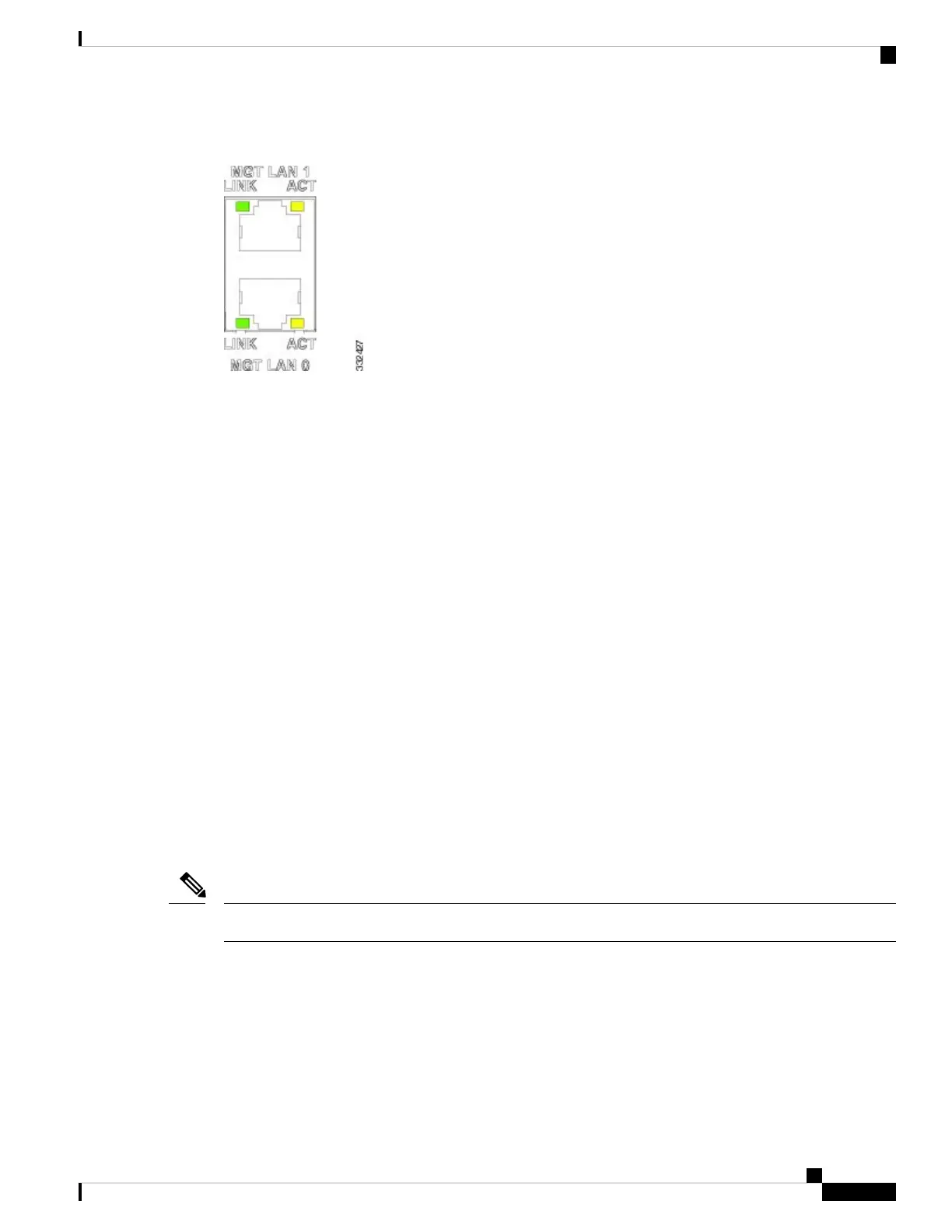
Figure 105: Management LAN Port Activity LEDs
Auxiliary and Console Ports
The auxiliary and console ports on the RP are EIA/TIA-232 (also known as RS-232) asynchronous serial
ports connect external devices to monitor and manage the system:
• Auxiliary port—RJ45 interface that supports flow control and is often used to connect a modem, a channel
service unit (CSU), or other optional equipment for Telnet management.
• Console port—Receptacle (female) that provides a RJ45 interface for connecting a console terminal.
Monitoring Critical, Major, and Minor Alarm Status
Alarms warn of:
• Overtemperature condition on a component in the card
• Fan failure in the fan tray
• Overcurrent condition in a power supply
• Out-of-tolerance voltage on the card
The alarm LEDs are controlled by the CAN microcontoller software, which sets the threshold levels for
triggering the different stages of alarms.
The RP card continuously polls the system for temperature, voltage, current, and fan speed values. If a threshold
value is exceeded, the RP sets the appropriate alarm severity level on the alarm card, which lights the
corresponding LED, and energizes the appropriate alarm display relays to activate any external audible or
visual alarms wired to the alarm display. The RP also logs a message about the threshold violation on the
system console.
If one or more of the alarm LEDs is on, check the system console for messages describing the alarm.
Note
Cisco ASR 9901, ASR 9001, and ASR 9001-S Routers Hardware Installation Guide
121
Troubleshooting the Installation
Auxiliary and Console Ports

 Loading...


