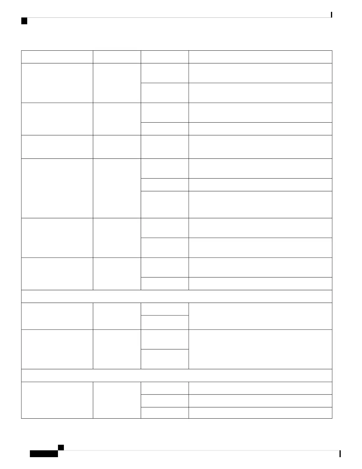
DescriptionColorLEDIndicator (Label)
External USB is busy/active. The LED is driven by the USB
controller.
Green
Single colorExternal USB 2.0 (EUSB)
(Cisco ASR 9001)
External USB is not busy/active.Off (Default after
reset)
Internal Solid State Hard Disk Drive (SSD0) is busy/active.
The LED is driven by the SSD/SAS controller.
Green
Single colorInternal Solid State Hard
Disk Drive (SSD)
(Cisco ASR 9901 only)
Internal Solid State Hard Disk Drive is not busy/active.Off
Alarm Cutoff is not enabled.
Note: ACO LED is not in use and will always be OFF.
Off
Single colorAlarm Cutoff (ACO)
(Cisco ASR 9001)
Sync - Time core is synchronized to an external source (either
GPS or IEEE1588).
GreenBi-colorSynchronization (SYNC)
Not used.Amber
Time core clock synchronization is either disabled OR Time
core is synchronized with external source excluding GPS
and IEEE1588
Off (Default after
reset)
GPS interface provisioned and ports are turned on. ToD, 1
PPS, 10 Mhz are all valid.
Green
Single colorGPS
(Cisco ASR 9901 only)
Either the interface is not provisioned, or the ports are not
turned on. ToD, 1 PPS, 10 Mhz are not valid.
Off (Default after
reset)
One (or more) fan tray does not have set speed, is
experiencing power fault, or is not inserted.
Red
Single colorFan fault (FAN FLT)
(Cisco ASR 9901 only)
All fan trays performing normally without speed variations.Off
Power Module
See Figure 100: Cisco ASR 9001 AC-Input Power Module
Status Indicators and Figure 102: Cisco ASR 9001 DC-Input
Power Module Status Indicators for detailed description
GreenBi-color
FAIL/OK
(ASR 9001 Power Module)
Amber
See Figure 99: Cisco ASR 9901 AC-Input Power Module
Status Indicators and Figure 101: Cisco ASR 9901 DC-Input
Power Module Status Indicators for detailed description
Green (solid or
flashing)
Bi-color
OK
(ASR 9901 Power Module)
Amber (solid or
flashing)
Fan Tray
Fan tray power ON state.AmberBi-color
STATUS (Fan tray)
Fan tray fully functional.Green
Fan failure condition.Red
Cisco ASR 9901, ASR 9001, and ASR 9001-S Routers Hardware Installation Guide
118
Troubleshooting the Installation
RP Front Panel Indicators

 Loading...


