11-15
Catalyst 6500 Series Content Switching Module Configuration Note
OL-4612-01
Chapter 11 Configuring Firewall Load Balancing
Configuring Stealth Firewall Load Balancing
Configuring Virtual Servers on CSM B
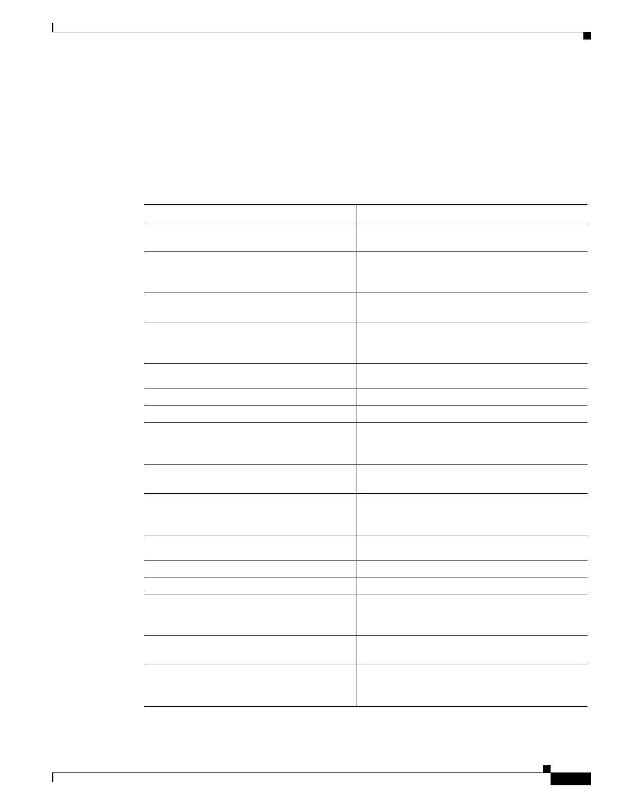
To configure three virtual servers on CSM, perform this task:
2. This step is required when configuring a server farm that contains a forwarding policy rather than real servers.
3. OUTSIDE-SF contains the two alias IP addresses of CSM A as the real servers allowing traffic from the intranet to reach
CSM A.
4. This step is required when configuring a server farm that contains a forwarding policy rather than real servers.
5. SERVERS-SF contains the IP addresses of the real servers located within the intranet.
Command Purpose
Step 1
Switch-B(config)# module csm 6
Enters multiple module configuration mode and
specifies that CSM B is installed in slot 6.
Step 2
Switch-B(config-module-csm)# vserver
FORWARD-VS-102
Specifies FORWARD-VS as the virtual server that is
being configured and enters virtual server
configuration mode.
Step 3
Switch-B(config-slb-vserver)# virtual
0.0.0.0 0.0.0.0 any
Specifies a match for any IP address and any
protocol
1
.
Step 4
Switch-B(config-slb-vserver)# vlan 102
Specifies that the virtual server will only accept
traffic arriving on VLAN 102, which is traffic
arriving from the secure side of the Firewall 1.
Step 5
Switch-B(config-slb-vserver)# serverfarm
FORWARD-SF
Specifies the server farm for this virtual server
2
.
Step 6
Switch-B(config-slb-vserver)# inservice
Enables the virtual server.
Step 7
Switch-B(config-slb-vserver)# exit
Returns to multiple module configuration mode.
Step 8
Switch-B(config-module-csm)# vserver
FORWARD-VS-104
Specifies FORWARD-VS
3
as the virtual server that
is being configured and enters virtual server
configuration mode.
Step 9
Switch-B(config-slb-vserver)# virtual
0.0.0.0 0.0.0.0 any
Specifies a match for any IP address and any
protocol
1
.
Step 10
Switch-B(config-slb-vserver)# vlan 104
Specifies that the virtual server will only accept
traffic arriving on VLAN 104, which is traffic
arriving from the secure side of the Firewall 2.
Step 11
Switch-B(config-slb-vserver)# serverfarm
FORWARD-SF
Specifies the server farm for this virtual server
2
.
Step 12
Switch-B(config-slb-vserver)# inservice
Enables the virtual server.
Step 13
Switch-B(config-slb-vserver)# exit
Returns to multiple module configuration mode.
Step 14
Switch-B(config-module-csm)# vserver
INSIDE-VS
Specifies INSIDE-VS
4
as the virtual server that is
being configured and enters virtual server
configuration mode.
Step 15
Switch-B(config-slb-vserver)# virtual
0.0.0.0 0.0.0.0 any
Specifies a match for any IP address and any
protocol
1
.
Step 16
Switch-B(config-slb-vserver)# vlan 20
Specifies that the virtual server will only accept
traffic arriving on VLAN 20, which is traffic arriving
from the intranet.
 Loading...


