2-25
Cisco ONS SONET TL1 Command Guide, R6.0
Chapter 2 Procedures and Provisioning
2.3 TL1 Gateway
Note • The <AID> provided in the CONN-TACC command designates the E side and the other
automatically becomes the F side.
• In the case of all 1-way circuits (1-way, UPSR_HEAD, UPSR_DROP,UPSR_DC, UPSR_EN):
–
If the AID specified is the source AID, the direction is designated as from E in the above table.
–
If the AID specified is the destination AID or the drop side, the direction is designated as from
F in the above table.
2.3 TL1 Gateway
This section describes the TL1 Gateway and provides procedures and examples for implementing
TL1 Gateway on the ONS 15454, ONS 15327, ONS 15310-CL, and ONS 15600.
2.3.1 Gateway Network Element Topology
You can issue TL1 commands to multiple nodes via a single connection through the TL1 Gateway. Any
node can serve as a Gateway Network Element (GNE), End Network Element (ENE), or Intermediate
Network Element (INE). A node becomes a GNE when a TL1 user connects to it and enters a command
destined for another node. An ENE is an end node because it processes a TL1 command that is passed
to it from another node. An INE is an intermediate node because of topology; it has no special hardware,
software, or provisioning.
To implement the TL1 Gateway, use the desired ENE’s TID in the ACT-USER command to initiate a
session between the GNE and the ENE. Once a session is established you need to enter the ENE’s TID
in all of the subsequent commands that are destined for the ENE. From the GNE, you can access several
remote nodes which become the ENEs. The ENEs are the message destinations or origins. The INE
handles the DCC TCP/IP packet exchange.
The GNE Session is the connection that multiplexes TL1 messages between the OSS/craftsperson and
the GNE. The GNE demulitplexes incoming operations support system (OSS) TL1 commands and
forwards them to the remote ENE. The GNE also multiplexes incoming responses and autonomous
messages to the GNE Session. The ENE Session is the connection that exchanges messages between the
GNE and the remote ENE. Figure 2-25 shows the GNE topology.
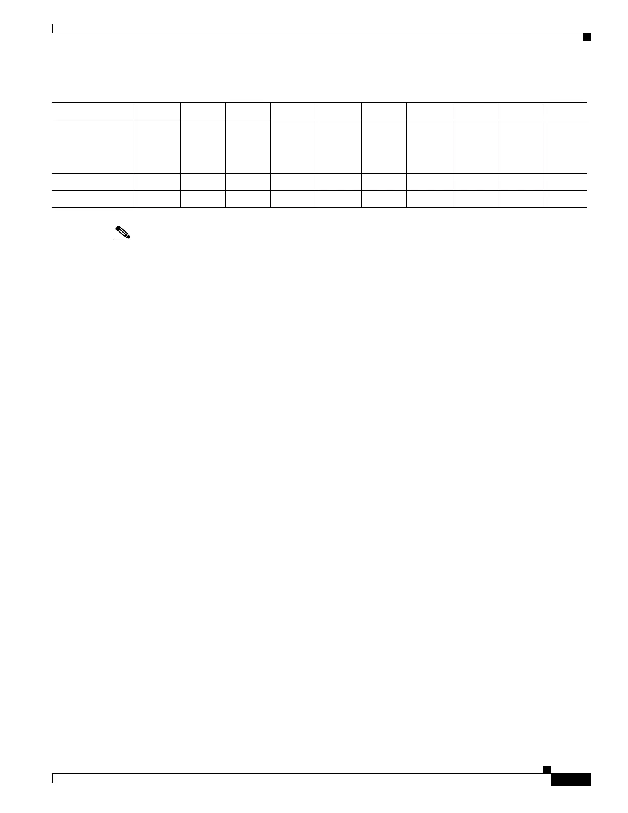
UPSR_DROP
UPSR_DC
UPSR_EN
(from F)
—X ———————X
UPSR_UPSRXXXXXXXXXX
Unmapped AIDX ——X ——X ———
Table 2-2 Modes Supported by Circuit Type (continued)
MONE MONF MONEF SPLTE SPLTF SPLTEF LOOPE LOOPF SPLTA SPLTB

 Loading...


